|
| Place of Origin: | America |
| Brand Name: | TYCO |
| Certification: | CE |
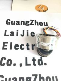
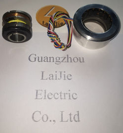
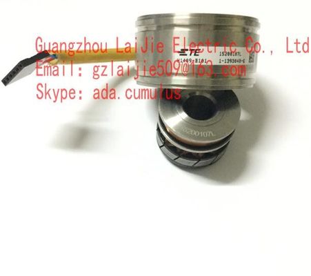
| Model Number: | V23401-H6009-B601 |
| Minimum Order Quantity: | 1pcs |
|---|---|
| Packaging Details: | CARTON |
| Delivery Time: | In stock |
| Payment Terms: | T/T, Western Union, MoneyGram |
| Supply Ability: | 10000PCS/WEEK |
| Material: | Iron | America: | America |
|---|---|---|---|
| V23401-H6009-B601: | V23401-H6009-B601 | TYCO: | TYCO |
| Wires: | 6wires | Temperature: | -50-120 |
Guang Zhou Lai Jie Electric Co.,LTD
Please contact with “Tommy” for the price
V23401-H6009-B601
V23401-T2409-C502
V23401-T2509-C202
V23401-T2609-C302
V23401-T2014-E209
V23401-T2629-E202
V23401-H1005-B001
V23401-T2509-C202
V23401-T2659-C302
V23401-T2669-C302
V23401-R3008-E101
V23401-S1201-B110
V23401-R3008-E101
V23401-D1001-B101
V23401-T2014-E209
V23401-T8002-B802
V23401-H2001-B202
V23401-D1001-B101
V23401-U7018-B709
V23401-H7002-B701
V23401-H6009-D601
V23401-T2014-B209
V23401-T2G09-E202
V23401-H6009-B601
V23401-D1001-B114
V23401-T2002-B209
V23401-T2009-B202
| Size | Pairs of Poles(Speed) | Angular error range | |||||||
| ±4' | ±6' | ±7' | ±8' | ±10' | ±15' | ±20' | Transformation ratio | ||
| 15 | 1 | X | X | X | X | 0.5 | |||
| 3 | X | X | X | X | 0.5 | ||||
| 1 | X | X | X | X | 0.5 | ||||
| 1 | X | X | X | X | 0.5 |
||||
![]()
Output impedance
Tolerance: ± 15 %
ZSO ... Impedance between S2 and S4 in a position of 0°
(minimal coupling) with open outputs
Tolerance: ± 15 %
ZSS ... Impedance between S1 and S3 in a position of 0°
(max. coupling) with short circuits between R1 and R2
When choosing the values of these parameters take into
account power dissipation, max. ambient temperature and
the heat dissipation. Including self heating a maximum
operating temperature of 150 °C must not be exceeded.
Generally a power dissipation of P ≤ 0.3 W is not critical.
Input current I
The adjacent figure applies to
VR1-R2 = 4 V.
For other input voltages, the input current
changes follows as:
I = I
Figure · VR1-R2 / 4 V
Power consumption P
The adjacent figure applies to
VR1-R2 = 4 V.
For other input voltages, the power
consumption changes follows as:
P = P
Figure · (VR1-R2 / 4 V)2
DC resistance
The ohmic resistance values are based on an RR1-R2 = 33 Ω
ambient temperature of 22 °C and change with RS1-S3 = RS2-S4 = 70 Ω
temperature by 0.39 % / K Tolerance: ± 10 %
| Input impedance Tolerance: ± 15 % |
ZRO ... Impedance between R1 and R2 with open outputs
| Tolerance: ± 15 % |
ZRS ... Impedance between R1 and R2 with short circuits
between S1 and S3 as well as between S2 and S4
Output impedance
Tolerance: ± 15 %
ZSO ... Impedance between S2 and S4 in a position of 0°
(minimal coupling) with open outputs
Tolerance: ± 15 %
ZSS ... Impedance between S1 and S3 in a position of 0°
(max. coupling) with short circuits between R1 and R2
Transformation ratio rT
rT = VS1-S3 max / VR1-R2
rT = VS2-S4 max / VR1-R2
ü = 0.5 ± 10 % within 4 ... 20 kHz
= 0.5 ± 5 % at 5 kHz