 |
| Place of Origin: | America |
| Brand Name: | TYCO |
| Certification: | CE |
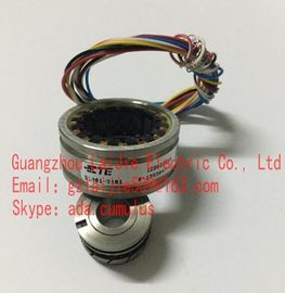
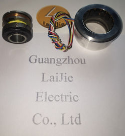
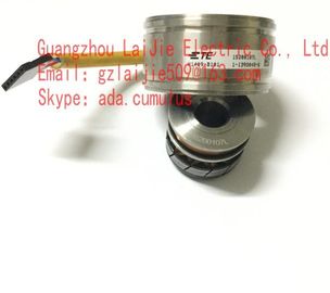
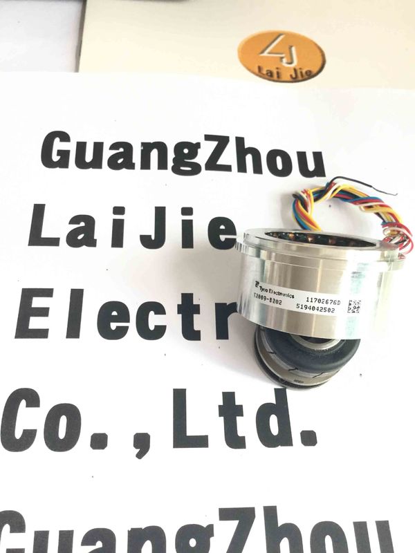
| Model Number: | V23401-D1001-B101 |
| Minimum Order Quantity: | 1pcs |
|---|---|
| Packaging Details: | Carton |
| Delivery Time: | In stock |
| Payment Terms: | Western Union, T/T, MoneyGram |
| Supply Ability: | 10000pcs/week |
| Material: | IRON | Clor: | Gray |
|---|---|---|---|
| Diameter: | 50mm | Temperature: | 20-120 |
| V23401-D1001-B101: | V23401-D1001-B101 | Wire: | 6 Wires |
| Tyco: | Tyco |
Guang Zhou Lai Jie Electric Co.,LTD
Please contact with “cumulus” for the price
![]()
![]()
![]()
![]()
| Model | Standard1 | Standard2 | Standard3 |
| Excitation Input | AC7Vrms 10kHz | ||
| Primary Side | R1 - R2 | ||
| Transformation Ratio | 0.286±10% | ||
| Electrical Error | 60'Max. | ||
| Input Impedance: Zro | 120Ω±20% |
||
V23401-D1001-B101
V23401-H2015-B202
V23401-U1016-B101
V23401-U1016-B109
V23401-U1016-B110
V23401-U1016-B133
V23401-U2017-B201
V23401-U2017-B202
V23401-U2017-B233
V23401-U2020-B201
V23401-U2020-B209
The product family architecture is modular. Depending on what is required from the encoder, the basic encoder and bus covers can be combined at will with the selected bus system. The basic encoders differ in terms of accuracy, ambient conditions and the utilized sensing principle
Bus cover
The bus cover accommodates the field bus interface and the complete electronics for processing the measured values. EtherNet/IP communication is performed via the specialized EtherNet/IP-ASIC ERTEC200 with integrated high-performance microcontroller ARM9.
Shaft encoders Mount the encoder by help of the mounting holes and three screws (square flange: 4 screws) provided at the encoder flange. Observe thread diameter and depth. There is an alternative mounting option in any angular position by eccentric fixings, see under accessories. Connect drive shaft and encoder shaft by using an appropriate coupling. The shaft ends must not touch each other. The coupling must compensate temperature and mechanical tolerances. Observe the maximum permitted axial or radial shaft load. For appropriate couplings please refer to accessories. Tighten the mounting screws firmly.
Mounting by clamping ring Prior to mounting the encoder open the clamping ring completely. Push encoder onto the drive shaft and tighten the clamping ring firmly. Adjusting element with rubber buffer Push the encoder onto the drive shaft and insert the cylindrical pin into the adjusting element (provided by customer) and the rubber buffer. Adjusting angle Push the encoder onto the drive shaft. Insert adjusting angle into the encoder’s rubber buffer and fasten the adjusting angle at the contact surface. Stud screw Push the encoder onto the drive shaft and insert the stud screw provided by customer into the encoder’s rubber buffer. Spring coupling Fasten the spring coupling at the mounting holes of the encoder housing using screws. Push the encoder onto the drive shaft and mount the spring coupling to the contact surface.
Seal up the unused cable gland using a sealing bolt (included in the delivery)
Importing the GSD file To implement the DP-Slave in the projecting software first the attached GSD file must be imported. All required modifications of basic settings are implemented by parameterization (see “Parameterization”). The GSD file itself is not modified. Step7® software is imported in the hardware window („Extras – install GSD-files“). Prior to the import operation the actual hardware project must be closed („Station - close“). Now the encoder appears at right in the hardware catalogue under „PROFIBUS-DP“ – „More field devices“ – „Encoder“ – (xx corresponding to the encoder type).
Important note for multiturn encoder operation This encoder supports „Endless Operation“ automatically if required. Thus, there are no special requirements for the encoder parameters “total measuring range” and “measuring units per revolution” to stand in a certain ratio. With endless operation active, the encoder shaft must not rotate when the encoder is not powered. In those cases where powerless motion cannot be avoided, the encoder has to be referenced (presetted) after each power-up. With Endless Operation inactive, the encoder shaft may rotate unlimited when encoder not powered.