|
| Place of Origin: | America |
| Brand Name: | TYCO |
| Certification: | CE |
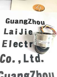
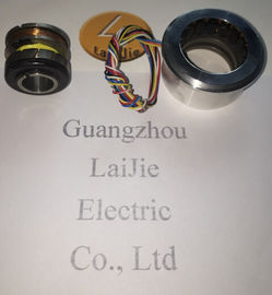
| Model Number: | V23401-H1005-D101 |
| Minimum Order Quantity: | 1pcs |
|---|---|
| Packaging Details: | carton |
| Delivery Time: | in stock |
| Payment Terms: | T/T, Western Union, MoneyGram |
| Supply Ability: | 10000pcs/week |
| TYCO: | TYCO | V23401-H1005-D101: | V23401-H1005-D101 |
|---|---|---|---|
| America: | America | Materia: | Iron |
| Color: | Black | Wires: | 6 Wires |
| Temperature: | -50-120 |
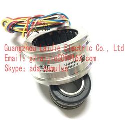
Guang Zhou Lai Jie Electric Co.,LTD
Please contact with “Tommy” for the price
V23401-T2014-E209
V23401-H1005-D101
V23401-H1005-D101
![]()
![]()
| Input impedance Tolerance: ± 15 % |
Tolerance: ± 15 % |
ZRO ... Impedance between R1 and R2 with open outputs ZRS ... Impedance between R1 and R2 with short circuits
between S1 and S3 as well as between S2 and S4
Power consumption P
The adjacent figure applies to
VR1-R2 = 4 V.
For other input voltages, the power
consumption changes follows as:
P = P
Figure · (VR1-R2 / 4 V)2
Output impedance
Tolerance: ± 15 % Tolerance: ± 15 %
ZSO ... Impedance between S2 and S4 in a position of 0° ZSS ... Impedance between S1 and S3 in a position of 0°
(minimal coupling) with open outputs (max. coupling) with short circuits between R1 and R2
V23401-T2099-C502
V23401-U2017-B201
V23401-U2017-B202
V23401-U2017-B233
V23401-U2020-B201
V23401-U2020-B209
V23401-D1001-B101
V23401-T2202-C309
V23401-T2014-B209
V23401-T2014-B209
V23401-T2G09-E202
V23401-H6009-B601
V23401-D1001-B114
V23401-T2002-B209
V23401-T2009-B202
V23401-T2014-B209
V23401-U1016-B110
V23401-T2014-E209
V23401-T2009-E202
V23401-U6119-B609
V23401-U6019-B609
V23401-S1201-C610
V23401-T2015-B201
V23401-H2009-B202
V23401-D1001-B114
V23401-D1001-B122
V23401-D1001-B101
V23401-D1001-B102
V23401-D1008-B114
End shaft/hollow shaft encoders Mounting by clamping ring Prior to mounting the encoder open the clamping ring completely. Push encoder onto the drive shaft and tighten the clamping ring firmly. Adjusting element with rubber buffer Push the encoder onto the drive shaft and insert the cylindrical pin into the adjusting element (provided by customer) and the rubber buffer. Adjusting angle Push the encoder onto the drive shaft. Insert adjusting angle into the encoder’s rubber buffer and fasten the adjusting angle at the contact surface. Stud screw Push the encoder onto the drive shaft and insert the stud screw provided by customer into the encoder’s rubber buffer. Spring coupling Fasten the spring coupling at the mounting holes of the encoder housing using scr
ews. Push the encoder onto the drive shaft and mount the spring coupling to the contact surface.
Mount the encoder by help of the mounting holes and three screws (square flange: 4 screws) provided at the encoder flange. Observe thread diameter and depth. There is an alternative mounting option in any angular position by eccentric fixings, see under accessories. Connect drive shaft and encoder shaft by using an appropriate coupling. The shaft ends must not touch each other. The coupling must compensate temperature and mechanical tolerances. Observe the maximum permitted axial or radial shaft load. For appropriate couplings please refer to accessories. Tighten the mounting screws firmly.
Ever store and transport the bus cover in the ESD bag only. For electrical connection remove the bus cover as follows: Release the fastening screws of the bus cover Carefully loosen the bus cover and lift off in an axial direction