|
| Place of Origin: | America |
| Brand Name: | TYCO |
| Certification: | CE |
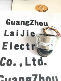
| Model Number: | V23401-T2509-C202 |
| Minimum Order Quantity: | 1pcs |
|---|---|
| Packaging Details: | CARTON |
| Delivery Time: | In stock |
| Payment Terms: | T/T, Western Union, MoneyGram |
| Supply Ability: | 10000PCS/WEEK |
| V23401-T2509-C202: | V23401-T2509-C202 | TYCO: | TYCO |
|---|---|---|---|
| America: | America | Material: | Iron |
| Temperature: | -50-120 | Wires: | 6wires |
| Color: | Black |
Guang Zhou Lai Jie Electric Co.,LTD
Please contact with “Tommy” for the price
V23401-T2509-C202
V23401-H2009-B222
V23401-T2009-B201
V23401-H2009-B201
V23401-T2009-B202
V23401-H2009-B202
V23401-T2010-B214
V23401-H2010-B214
V23401-T2010-B222
V23401-H2010-B222
V23401-T2010-B201
V23401-H2010-B201
V23401-T2010-B202
V23401-H2010-B202
V23401-T2014-B214
V23401-H2014-B214
V23401-T2014-B222
V23401-H2014-B222
V23401-T2014-B201
V23401-H2014-B202
V23401-T2014-B202
V23401-T2015-B214
V23401-H2015-B214
V23401-T2015-B222
V23401-H2015-B222
V23401-T2015-B201
V23401-H2015-B201
V23401-T2015-B202
V23401-H2015-B202
![]()
ZRO ... Impedance between R1 and R2 with open outputs ZRS ... Impedance between R1 and R2 with short circuits
between S1 and S3 as well as between S2 and S4
Output impedance
Tolerance: ± 15 % Tolerance: ± 15 %
ZSO ... Impedance between S2 and S4 in a position of 0° ZSS ... Impedance between S1 and S3 in a position of 0°
(minimal coupling) with open outputs (max. coupling) with short circuits between R1 and R2
Transformation ratio rT
rT = VS1-S3 max / VR1-R2
rT = VS2-S4 max / VR1-R2
ü = 0.5 ± 10 % within 2 ... 10 kHz
= 0.5 ± 5 % at 5 kHz
Phase shift ø
VR1-R2(t) = VR1-R2 max · sin(2 · ð · f · t)
VS1-S3(t) = VS1-S3 max · sin(2 · ð · f · t - ø)
for –90° < á < +90°
Tolerance: ± 5°
When choosing the values of these parameters take into
account power dissipation, max. ambient temperature and
the heat dissipation. Including self heating a maximum
operating temperature of 150 °C must not be exceeded.
Generally a power dissipation of P ≤ 0.5 W is not critical.
Input current I
The adjacent figure applies to
VR1-R2 = 7 V.
For other input voltages, the input current
changes follows as:
I = I
Figure · VR1-R2 / 7 V
Power consumption P
The adjacent figure applies to
VR1-R2 = 7 V.
For other input voltages, the power
consumption changes follows as:
P = P
Figure · (VR1-R2 / 7 V)2
DC resistance
The ohmic resistance values are based on an RR1-R2 = 24 Ω
ambient temperature of 22 °C and change with RS1-S3 = RS2-S4 = 58 Ω
temperature by 0.39 % / K Tolerance: ± 10 %
| Input impedance Tolerance: ± 15 % |
Tolerance: ± 15 % |
ZRO ... Impedance between R1 and R2 with open outputs ZRS ... Impedance between R1 and R2 with short circuits
between S1 and S3 as well as between S2 and S4
Output impedance
Tolerance: ± 15 % Tolerance: ± 15 %
ZSO ... Impedance between S2 and S4 in a position of 0° ZSS ... Impedance between S1 and S3 in a position of 0°
(minimal coupling) with open outputs (max. coupling) with short circuits between R1 and R2
Transformation ratio rT
rT = VS1-S3 max / VR1-R2
rT = VS2-S4 max / VR1-R2
ü = 0.5 ± 10 % within 2 ... 8 kHz
= 0.5 ± 5 % at 5 kHz