 |
| Place of Origin: | America |
| Brand Name: | TYCO |
| Certification: | CE |
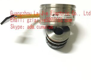
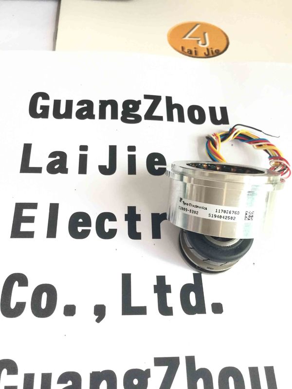
| Model Number: | V23401-U6319-B609 |
| Minimum Order Quantity: | 1pcs |
|---|---|
| Packaging Details: | carton |
| Delivery Time: | in stock |
| Payment Terms: | T/T, Western Union, MoneyGram |
| Supply Ability: | 10000pcs/week |
| TYCO: | TYCO | V23401-U6319-B609: | V23401-U6319-B609 |
|---|---|---|---|
| America: | America | Materia: | IRON |
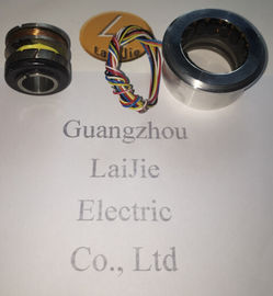
| Color: | Black | Wires: | 6 Wires |
| Temperature: | -50-120 |
Guang Zhou Lai Jie Electric Co.,LTD
Please contact with “Tommy” for the price
V23401-U6319-B609
V23401-H2009-B214
V23401-T2009-B222
V23401-H2009-B222
V23401-T2009-B201
V23401-H2009-B201
V23401-T2009-B202
V23401-H2009-B202
V23401-T2010-B214
V23401-H2010-B214
V23401-T2010-B222
V23401-H2010-B222
V23401-T2010-B201
V23401-H2010-B201
V23401-T2010-B202
V23401-H2010-B202
V23401-T2014-B214
V23401-H2014-B214
V23401-T2014-B222
V23401-H2014-B222
V23401-T2014-B201
V23401-H2014-B202
V23401-T2014-B202
V23401-T2015-B214
V23401-H2015-B214
V23401-T2015-B222
V23401-H2015-B222
V23401-T2015-B201
V23401-H2015-B201
![]()
| Input impedance Tolerance: ± 15 % |
Tolerance: ± 15 % |
Electrical commissioning Do not proceed any electrical modifications at the encoder. Do not proceed any wiring work while encoder is live. Never plug or unplug connector while encoder is live (the bus cover however may be removed or docked to the basic encoder when live). Ensure that the entire system is installed in line with EMC/EMI requirements. Operating environment and wiring have an impact on the electromagnetic compatibility of the encoder. Install encoder and supply cables separately or far away from sources with high emitted interference (frequency converters, contactors, etc). When working with consumers with high emitted interference provide separate encoder supply voltage.
Completely shield encoder housing and connecting cables.. Connect encoder to protective earth (PE) using shielded cables. The braided shield must be connected to the cable gland or connector. Ideally, aim at dual connection to protective earth (PE), i.e. housing by mechanical assembly and cable shield by the downstream devices. In case of earth loop problems, earth at least on one side.
The product family architecture is modular. Depending on what is required from the encoder, the basic encoder and bus covers can be combined at will with the selected bus system. The basic encoders differ in terms of accuracy, ambient conditions and the utilized sensing principle.
Mount the encoder by help of the mounting holes and three screws (square flange: 4 screws) provided at the encoder flange. Observe thread diameter and depth. There is an alternative mounting option in any angular position by eccentric fixings, see under accessories. Connect drive shaft and encoder shaft by using an appropriate coupling. The shaft ends must not touch each other. The coupling must compensate temperature and mechanical tolerances. Observe the maximum permitted axial or radial shaft load. For appropriate couplings please refer to accessories. Tighten the mounting screws firmly.
| Input impedance Tolerance: ± 15 % |
Tolerance: ± 15 % |
Output impedance
Tolerance: ± 15 % Tolerance: ± 15 %
ZSO ... Impedance between S2 and S4 in a position of 0° ZSS ... Impedance between S1 and S3 in a position of 0°
(minimal coupling) with open outputs (max. coupling) with short circuits between R1 and R2