 |
| Place of Origin: | America |
| Brand Name: | TYCO |
| Certification: | CE |
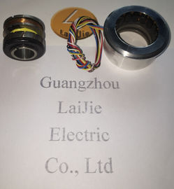
| Model Number: | V23401-T2099-C502 |
| Minimum Order Quantity: | 1pcs |
|---|---|
| Packaging Details: | carton |
| Delivery Time: | In stock |
| Payment Terms: | T/T, Western Union, MoneyGram |
| Supply Ability: | 10000pcs/week |
| TYCO: | TYCO | V23401-T2099-C502: | V23401-T2099-C502 |
|---|---|---|---|
| America: | America | Materia: | Iron |
| Colorl: | Black | Wires: | 6wires |
| Temperature: | -50-120 |
Guang Zhou Lai Jie Electric Co.,LTD
Please contact with “Tommy” for the price
V23401-T2099-C502
V23401-U2017-B201
V23401-U2017-B202
V23401-U2017-B233
V23401-U2020-B201
V23401-U2020-B209
V23401-D1001-B101
V23401-T2202-C309
V23401-T2014-B209
V23401-T2014-B209
V23401-T2G09-E202
V23401-H6009-B601
V23401-D1001-B114
V23401-T2002-B209
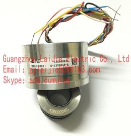
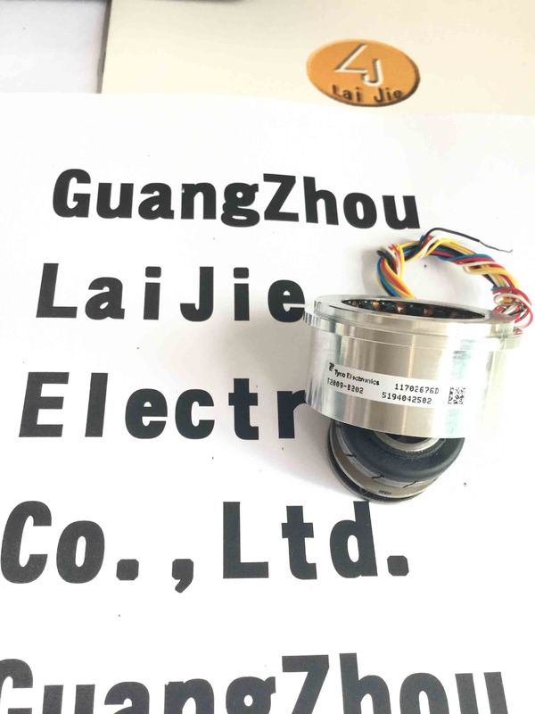
V23401-T2009-B202
V23401-T2014-B209
V23401-U1016-B110
V23401-T2014-E209
V23401-T2009-E202
V23401-U6119-B609
V23401-U6019-B609
V23401-S1201-C610
V23401-T2015-B201
V23401-H2009-B202
V23401-D1001-B114
V23401-D1001-B122
V23401-D1001-B101
V23401-D1001-B102
V23401-D1008-B114
| Input impedance Tolerance: ± 15 % |
Tolerance: ± 15 % |
ZRO ... Impedance between R1 and R2 with open outputs ZRS ... Impedance between R1 and R2 with short circuits
between S1 and S3 as well as between S2 and S4
Power consumption P
The adjacent figure applies to
VR1-R2 = 4 V.
For other input voltages, the power
consumption changes follows as:
P = P
Figure · (VR1-R2 / 4 V)2
Output impedance
Tolerance: ± 15 % Tolerance: ± 15 %
ZSO ... Impedance between S2 and S4 in a position of 0° ZSS ... Impedance between S1 and S3 in a position of 0°
(minimal coupling) with open outputs (max. coupling) with short circuits between R1 and R2![]()
Supplementary information The present manual is intended as a supplement to already existing documentation (catalogues, product data sheets and mounting instructions). The manual must be studied carefully prior to initial commissioning of the equipment. Intended purpose of the equipment The encoder is a precision measurement device. It is utilized to determine angular positions and revolutions, and to prepare and supply measured values in the form of electrical output signals for the downstream device. Encoders may only be used for this purpose. Commissioning The encoder must be initialised and mounted only by a qualified expert. Observe the operating instructions of the machine manufacturer. Safety instructions Check all electrical connections prior to commissioning of the equipment. If mounting, electrical connections or any other work performed at the encoder and the equipment is not correctly executed this can result in malfunction or failure of the encoder. Corresponding safety precautions must be provided and observed to exclude any risk of personal injury, damage to material or operating equipment as a result of encoder failure or malfunction. Encoders must not be operated outside the specified limited values (see further documentation).
Transport and storage Only ever transport or store the encoder in its original packaging. Never drop the encoder nor expose it to major shocks.
Avoid impacts or shocks on housing and shaft/end shaft. End shaft/Hollow shaft encoder: Open clamping ring completely before mounting the encoder Avoid any twist or torsion on the housing. Shaft encoders: never make rigid connections between encoder shaft and drive shaft. Do not open the encoder or proceed any mechanical modifications.
Electrical commissioning Do not proceed any electrical modifications at the encoder. Do not proceed any wiring work while encoder is live. Never plug or unplug connector while encoder is live (the bus cover however may be removed or docked to the basic encoder when live). Ensure that the entire system is installed in line with EMC/EMI requirements. Operating environment and wiring have an impact on the electromagnetic compatibility of the encoder. Install encoder and supply cables separately or far away from sources with high emitted interference (frequency converters, contactors, etc). When working with consumers with high emitted interference provide separate encoder supply voltage. Completely shield encoder housing and connecting cables.. Connect encoder to protective earth (PE) using shielded cables. The braided shield must be connected to the cable gland or connector. Ideally, aim at dual connection to protective earth (PE), i.e. housing by mechanical assembly and cable shield by the downstream devices. In case of earth loop problems, earth at least on one side.