|
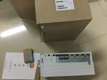
| Place of Origin: | GERMANY |
| Brand Name: | LENZE |
| Certification: | CE |
| Model Number: | E94ASHE4604 |
| Minimum Order Quantity: | 1PCS |
|---|---|
| Packaging Details: | CARTON |
| Delivery Time: | IN STOCK |
| Payment Terms: | T/T, Western Union, MoneyGram |
| Supply Ability: | 100PCS/WEEK |
| LENZE: | LENZE | E94ASHE4604: | E94ASHE4604 |
|---|---|---|---|
| GERMANY: | GERMANY | Material: | Iron |
| Color: | Black | Temperature: | 20-90 |
| Dimension: | 80mm |
![]()
![]()
![]()
![]()
| Gate control The opening and closing of the hardware gate (HW gate) and software gate (SW gate) defines the period of time during which the counting signals are acquired. |
|
| evaluates the acquired encoder signals and provides them for Motion Control. In the hardware configuration of the CPU 1511C-1 PN in STEP 7 (TIA Portal), select the |
|
| Position input for Motion Control" mode. Reference |
The digital inputs of the digital on-board I/O control the HW gate. The user program controls
the software gate. You can enable the hardware gate using the parameter assignment. The
software gate (bit in the control interface of the cyclic I/O data) cannot be disabled.
Capture
You can configure an external reference signal edge that triggers the saving of the current
count value as a Capture value. The following external signals can trigger the Capture
function:
● Rising or falling edge of a digital input
● Both edges of a digital input
● Rising edge of signal N at the encoder input
You can configure whether counting continues from the current count value or from the start
value after the Capture function.You can specify hysteresis for the comparison values, within which a digital output is
prevented from switching again. An encoder may stop at a certain position, and slight
movements may make the count value fluctuate around this position. If a comparison value
or a counting limit lies within this fluctuation range, the corresponding digital output will be
switched on and off often if hysteresis is not used. The hysteresis prevents these unwanted
switching operations.
Reference
For more information on the counter, refer to the , ET 200MP, ET 200SP Counting,
measurement and position detection function manual A measuring interval calculates the average frequency based on the time sequence of the count
pulses, and returns this frequency as a floating-point number in units of hertz.
Period measurement A measuring interval calculates the average period duration based on the time sequence of the
count pulses, and returns this period duration as a floating-point number in units of seconds.
Velocity measurement A measuring interval calculates the average velocity based on the time sequence of the count
pulses, and returns this velocity in the configured unit.
The measured value and count value are both available in the feedback interface.
Update time
You can configure the interval at which the compact CPU updates the measured values
cyclically as the update time. Greater update times smooth uneven measured variables and
increase the measuring accuracy.
Gate control
Opening and closing the hardware gate and software gate defines the period of time during
which the count signals are acquired. The update time is asynchronous to the opening of the
gate, which means that the update time is not started when the gate is opened. After the
gate is closed, the last measured value calculated is still returned.All measured values are returned as signed values. The sign indicates whether the count
value increased or decreased during the relevant time period. For example, a value of -
80 Hz means that the count value decreases at 80 Hz.You can use the digital on-board I/O, e.g. with an incremental encoder, for position detection
with Motion Control. The position detection is based on the counting function, which