 |
| Place of Origin: | GERMANY |
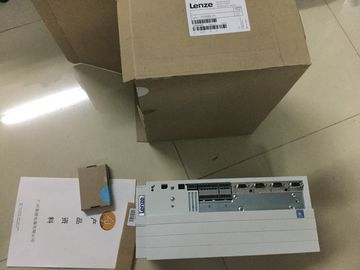
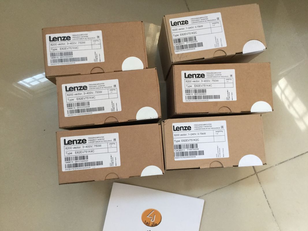
| Brand Name: | LENZE |
| Certification: | CE |
| Model Number: | EVS9322-ETV100 |
| Minimum Order Quantity: | 1pcs |
|---|---|
| Packaging Details: | carton |
| Delivery Time: | in stock |
| Payment Terms: | T/T, Western Union, MoneyGram |
| Supply Ability: | 100pcs/week |
| LENZE: | LENZE | Material: | Iron |
|---|---|---|---|
| Color: | Black | Temperature: | 20-90 |
| Dimension: | 80mm | EVS9322-ETV100: | EVS9322-ETV100 |
| Wire: | Wire |
![]()
![]()
![]()
![]()
| The number of generated pulses is based on the number of 0-to-1 transitions from phase A. The phase ratio determines the direction of motion:● PTO (A, B phase-shifted - quadruple): |
|
| When you select the PTO signal type (A, B phaseshifted, quadruple), the two outputs transmit pulses with the specified velocity, but phaseshifted by 90 degrees. The quadruple signal type is a 4x configuration in which each edge |
|
| transition corresponds to an increment. Therefore, a full period of the signal A contains four increments. In this way, two outputs, each with 100 kHz signal frequency, can be used to output a control signal that supplies 400 000 increments per second. The |
direction is determined based on the output which first changes from 0 to 1. With positive
direction, A precedes B. With negative direction B precedes AWith the parameter
"Missing supply voltage
L+", you activate the
diagnostic interrupt of
the channel in the event
of no supply voltage L+.
Deactivated Deactivated
Activated
Data exchange
with
the drive
Reference speed With the parameter
"Reference speed", you
define the reference
value for the drive velocity.
The drive velocity
is defined as percentage
value of the reference
speed in the
range from -200% to
+200%.
Floating-point number:
1.0 to 20 000.0 (rpm)
3 000.0 (rpm)
Maximum speed The parameter "Maximum
speed" is used to
define the required
maximum speed for
your application.
The supported value range depends
on:
• the signal type selected under
"Operating mode"
• the value defined under "Increments
per revolution"
• the value defined under "Reference
speed"
The low limit of the value range
is:
• for the signal type "PTO (A, B
phase-shifted - quadruple)":
0.1 Hz * 60 s/min * 4) / Increments
per revolution
• for the non-quadruple PTO
signal types: (0.1 Hz *
60 s/min) / Increments per
revolution
The high limit of the value range
is the minimum of the value:
• 2 * reference speed
and of the value:
• for the signal type "PTO (A, B
phase-shifted - quadruple)":
(100 000 Hz * 60 s/min * 4) /
Increments per revolution
• for the non-quadruple PTO
signal types:
(100 000 Hz * 60 s/min) / Increments
per revolutionIncrements per revolution
The "Increments per
revolution" is used to
define the number of
increments per revolution
(also in microstep
mode), which is required
by the drive for a
revolution.
1 to 1 000 000 200
Fine resolution Bits in incr. actual value
(G1_XIST1)
The parameter defines
the number of bits for
the coding of the fine
resolution in the current
incremental value of
G1_XIST1.
0 0
Stop behavior Quick stop time The parameter "Quick
stop time" defines the
time period within which
the drive should go
from the maximum
speed to a standstill
(OFF3).
1 to 65 535 (ms) 1 000 (ms)
Hardware
inputs/
outputs
Reference switch input The parameter "Reference
switch input" defines
the hardware input
of the reference switch.
[Input address of the reference
switch DI]
--
Edge selection reference
switch
The parameter "Edge
selection reference
switch" defines the
edge type which is to
be detected by the
reference switch.
Rising edge Rising edge
Falling edge
Measuring input The parameter "Measuring
input" defines the
hardware input of the
measuring input.
[Input address of the measuring
input DI]
--
"Drive ready" input The parameter ""Drive
ready" input" defines
the hardware input of
the input "Drive ready".
[Input addresses of the inputs
"Drive ready" DIn]
--
Pulse output A