 |
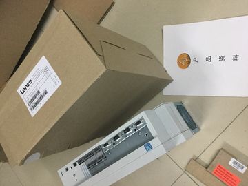
| Place of Origin: | GERMANY |
| Brand Name: | LENZE |
| Certification: | CE |
| Model Number: | EVS9323- ESV004 |
| Minimum Order Quantity: | 1pcs |
|---|---|
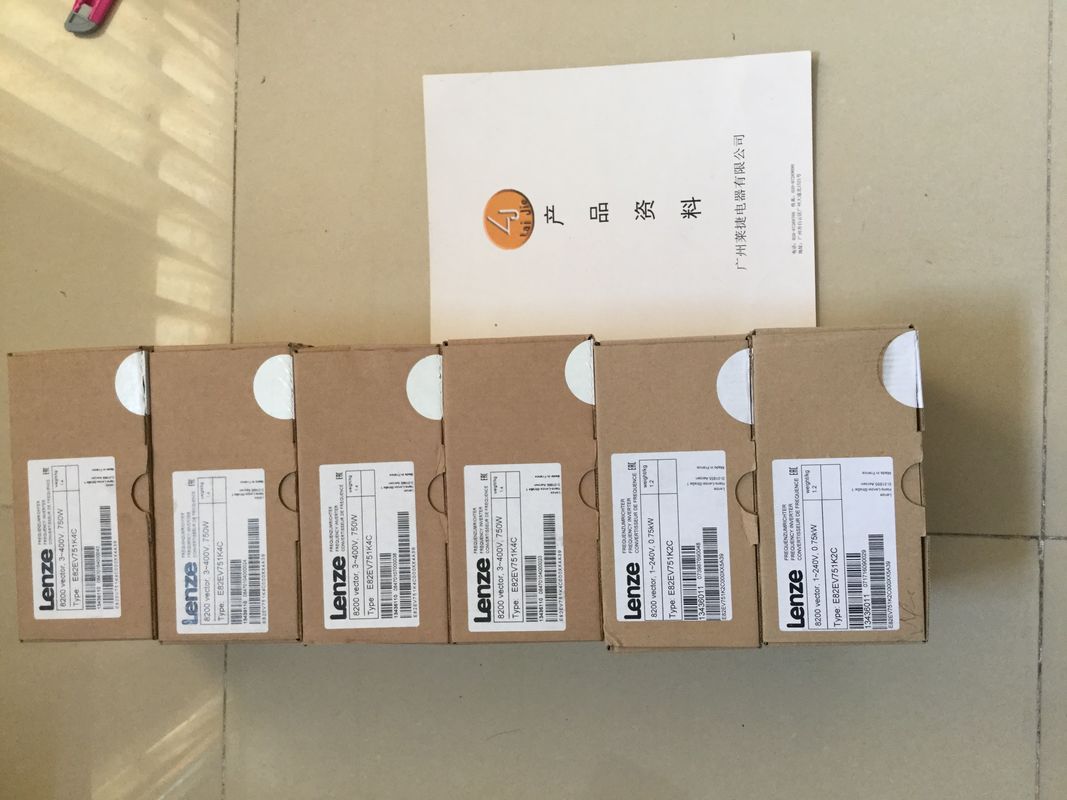
| Packaging Details: | carton |
| Delivery Time: | in stock |
| Payment Terms: | T/T, Western Union, MoneyGram |
| Supply Ability: | 100ps/week |
| LENZE: | LENZE | EVS9323- ESV004: | EVS9323- ESV004 |
|---|---|---|---|
| Material: | Iron | Temperature: | 20-90 |
| Dimension: | 80mm | Germany: | Germany |
![]()
![]()
![]()
![]()
| for "PTO (pulse (A) and direction B)" The parameter "Pulse |
|
| output A" defines the hardware output for PTO signal A. |
|
| [Output address DQ for PTO signal A (output frequency 100 |
kHz)]
Grayed out
Read only access
to the parameter
Direction output B
for "PTO (pulse (A) and
direction B))"
The parameter "Direction
output B" defines
the hardware output for
PTO signal B.
[Output address 1 of the DQ for
PTO signal B (output frequency
100 kHz)]
Qn (output frequency
100 kHz)
[Output address 2 of the DQ for
PTO signal B (output frequency
100 kHz)]Count up
for "PTO (Count up (A)
and Count down (B))"
The "Clock generator
forward (A)" parameter
defines the hardware
output for PTO signal A.
[Output address DQ for PTO
signal A (output frequency 100
kHz)]
Grayed out
Read only access
to the parameter
Count down
for "PTO (Count up (A)
and Count down (B))"
The "Clock generator
backward (B)" parameter
defines the hardware
output for PTO
signal B.
[Output address 1 of the DQ for
PTO signal B (output frequency
100 kHz)]
Grayed out
Read only access
to the parameter
Phase A
for "PTO (A, B phaseshifted)"
and "PTO (A, B
phase-shifted, quadruple)"
The "Clock generator
output (A)" parameter
defines the hardware
output for PTO signal A.
[Output address of the DQ for
PTO signal A (output frequency
100 kHz)]
Grayed out
Read only access
to the parameter
Phase B
for "PTO (A, B phaseshifted)"
and "PTO (A, B
phase-shifted, quadruple)"
The "Clock generator
output (B)" parameter
defines the hardware
output for PTO signal B.
[Output address 1 of the DQ for
PTO signal B (output frequency
100 kHz)]
Grayed out
Read only access
to the parameter
Drive enable output The parameter "Drive
enable output" defines
the hardware output of
the output "Drive enable
output".
[Output addresses of the enable
outputs DQn (output frequency
100 Hz)]
--
Reaction of the PTO channel to CPU STOP
The PTO channel reacts to a change to CPU STOP by removing the drive enable (if the
drive enable output is configured) and outputting the velocity setpoint 0 at the hardware
outputs configured for the signal tracks A and B. The CPU STOP reaction of the PTO
channels cannot be configured.
Note
Reaction to CPU STOP
Upon CPU STOP, the hardware outputs assigned for the PTO outputs A and B can switch to
signal state 'High' (1) and/or remain there. It is not guaranteed that the two hardware outputs
switch to/remain in signal level 'Low' (0).The pulse output channels for the four modes of the pulse generators (PTO) are controlled
using Motion Control via the technology objects TO_SpeedAxis, TO_PositioningAxis and
TO_SynchronousAxis. With these operating modes, the control and feedback interface of the
channels is a partial implementation of the PROFIdrive interface "Telegram 3". For a detailed
description of the use of motion control and its configuration, refer to the Motion
Control function manuaThe function "High-speed output (0.1 A)" improves the signal clock of the digital outputs
(DQ0 to DQ7). Less delay, fluctuation, jitter, and shorter rise and fall times occur at the