|
| Place of Origin: | GERMANY |
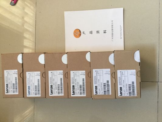
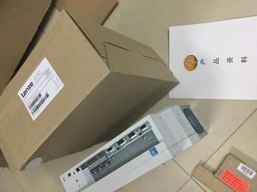
| Brand Name: | LENZE |
| Certification: | CE |
| Model Number: | EVS9323-EI |
| Minimum Order Quantity: | 1pcs |
|---|---|
| Packaging Details: | carton |
| Delivery Time: | in stock |
| Payment Terms: | T/T, Western Union, MoneyGram |
| Supply Ability: | 100pcs/week |
| LENZE: | LENZE | EVS9323-EI: | EVS9323-EI |
|---|---|---|---|
| Material: | Iron | Color: | Black |
| Temperature: | 20-90 | Dimension: | 80mm |
| Wire: | Wire |
![]()
![]()
![]()
![]()
| STEP 7 (TIA Portal). You can also change the parameter assignment during runtime with the help of the program via the data record. |
|
| For the PWM and Frequency output modes, select the high-speed output of the channel in | |
| High-speed pulse output (high-speed output) is available for the following operating modes: ● PWM ● Frequency output |
PTO (the pulse outputs for the PTO mode are always "High-speed output (0.1 A)")In the modes "Pulse width modulation PWM" and "Frequency output", you can set the pulse
output (DQA) of a pulse generator directly via the control program. Select the function for the
DQ direct control by deleting the output control bit of the PWM channel (TM_CTRL_DQ = 0)
in the control interface.
The direct control of the pulse output (DQA) can be helpful when commissioning a control
system for automation.
When you select the direct control of the pulse output (DQA) during a pulse output
sequence, the sequence continues to run in the background so that the output sequence is
continued as soon as the channel takes control again (by setting TM_CTRL_DQ = 1).
You assign the status of the pulse output (DQA) using the control bits SET_DQA.
When you set TM_CTRL_DQ = 1, you deselect the direct control of the pulse output (DQA)
and the channel takes over the processing. If the output sequence is still running
(STS_ENABLE still active), the PWM channel takes over the control of the output again. If
TM_CTRL_DQ = 1 and STS_ENABLE is not active, the module's channel also takes over
processing, but then outputs "0".utput control signal TM_CTRL_DQ of the PWM channel
• If TM_CTRL_DQ = 1, the technology function takes over the control and generates pulse
sequences at the output PWM DQA.
• If TM_CTRL_DQ = 0, the user program takes over the control and the user can set the
PWM DQA directly using the control bits SET_DQA.The user program influences the behavior of the PWM channel through the control interface.
Control interface per channel
The following table shows the control interface assignment: Transfer the control for the output to the PWM channel.
2. Set SW_ENABLE so that the output can be started.
3. Set the required on-load factor using OUTPUT_VALUE.
4. If necessary, change the period duration (cyclically or once). If you do not change the
value, the period duration from the hardware configuration will be used.
5. With TM CTRL_DQ and SET_DQ, set the output from the user program permanently to 1
or 0.
6. Acknowledge any errors that occur using RES_ERROR.
Additional parameters for the output sequence are defined before the start of an output
sequence.
The data record of the parameter assignment is changed in the device configuration in
STEP 7 (TIA Portal) or through WRREC execution.The interpretation of the value OUTPUT_VALUE depends on the set operating mode.
OUTPUT_VALUE is always updated. When an invalid value is detected (outside the
permissible range), the error memory bit ERR_OUT_VAL is set until a valid value is
detected. During the error condition, the invalid value is ignored and the PWM channel
continues with the last valid OUTPUT_VALUE. Note that, in the frequency output mode, it is
also possible that no last valid value is available. In this case, the pulse output returns the
value 0, i.e. there is no pulse output.
Please note that the on-load factor is not checked in PWM mode. If the on-load factor is
greater than the format permits, the PWM channel uses a ratio of 100%. For values < 0, 0%
is effective.
SLOT, MODE_SLOT and LD_SLOT
Use these control interface fields if you occasionally change the period duration in PWM
mode before the start of the output sequence or during operation. You can find a description
of the interaction between SLOT, MODE_SLOT and LD_SLOT under Handling the SLOT
parameter (control interface) (Page 73).
SW_ENABLE
If 0 → 1, activate the output sequence.If 1, the output is controlled by the PWM channel and generates the pulse sequences
● If 0, the output is controlled directly by the program using the SET_DQA assignmentsT_DQA
● If 1, set the output A to 1, if TM_CTRL_DQ is inactive
● If 0, set the output A to 0, if TM_CTRL_DQ is inactive
RES_ERROR
Resetting the error bit memory ERR_LD in the feedback interface
3.2.3.2 Handling the SLOT parameter (control interface)
SLOT and MODE_SLOT
SLOT has the following operating modes.
● Mode for individual update (MODE_SLOT = 0)
Use this mode if you occasionally change the specific parameters (such as period
duration) before the start of the output sequence or during operation.
– The value in SLOT is always applied when the value changes in LD_SLOT.
– The acknowledgment bit STS_LD_SLOT in the feedback interface is switched.
– The value of LD_SLOT defines the interpretation of SLOT (see the table below
"Interpretation of the SLOT parameter value").
– If the LD_SLOT value is invalid, the setting of the feedback bit ERR_LD indicates a
parameter assignment error. The user has to reset the error using the control bit
RES_ERROR and enable the SLOT parameter again for the next value.
– Changes made in this mode can be read back by the channel to the parameter
assignment data record.
– The current changes are entered in the data record 128 during readback of the
parameter assignment data from the user program with RDREC. These changes are
lost during a warm restart of the CPU.
● Mode for cyclic updating (MODE_SLOT = 1)
Use this operating mode if the program is to continuously control another parameter in
addition to the main parameter to be controlled.
– The value in SLOT is transferred with each module cycle.