 |
| Place of Origin: | GERMANY |
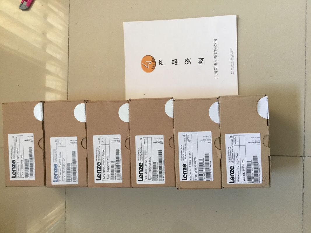
| Brand Name: | LENZE |
| Certification: | CE |
| Model Number: | EVS9323-EK |
| Minimum Order Quantity: | 1pcs |
|---|---|
| Packaging Details: | carton |
| Delivery Time: | in stock |
| Payment Terms: | T/T, Western Union, MoneyGram |
| Supply Ability: | 100pcs/week |
| LENZE: | LENZE | EVS9323-EK: | EVS9323-EK |
|---|---|---|---|
| GERMANY: | GERMANY | Material: | Iron |
| Color: | Black | Temperature: | 20-90 |
| Dimension: | 80mm |
![]()
![]()
![]()
![]()
| No acknowledgment bit is available. – The value of LD_SLOT defines the interpretation of SLOT (see the table below |
|
| Interpretation of the SLOT parameter value"). – If the value in SLOT is not valid, the error ERR_SLOT_VAL occurs. The error is |
|
| automatically reset as soon as a valid value is loaded. – In this mode, the value in the parameter assignment data record is not updated. If |
LD_SLOT is changed in this mode, the last value applied from LD_SLOT is valid.
– The mode for permanent updating can be stopped by setting LD_SLOT to 0 and
MODE_SLOT to 0. By stopping the mode for permanent updating, the changes made
at the parameters during permanent updating are retained until the next changes via
SLOT (cyclic or once) or until the next STOP-RUN transition.The following representation illustrates the sequence of the individual updating of the
parameter 'Period duration'. The described workflow principle can also be used on the
channels of the high-speed counters.User writes the first parameter in SLOT and specifies the first parameter in LD_SLOT
② Technology channel applies the first parameter and indicates the application with a change in
the bit STS_LD_SLOT
③ User writes the second parameter in SLOT and specifies the second parameter in LD_SLOT
④ Technology channel applies the second parameter and indicates the application with a change
in the bit STS_LD_SLOT
⑤ User writes 0 in LD_SLOT, (SLOT inactive)
⑥ Technology channel answers change in LD_SLOT with a change in STS_LD_SLOT
Figure 3-4 Individual updating
Note that the following requirements apply to the representation shown above:
● The value MODE_SLOT must be set to 0
● Errors or invalid values are shown in the feedback bit ERR_SLOT_VAL
● The error must be acknowledged
If MODE_SLOT 0 = 1, the following applies (for PWM mode only):
● The value in SLOT is continuously evaluated according to LD_SLOT
● STS_LD_SLOT does not change
● An error is automatically reset as soon as a valid value is set in SLOTUser sets SLOT to the required parameter
• User sets MODE_SLOT to 1
• User sets LD_SLOT to the required value (1 for period duration)
② User changes value in SLOT continuously and technology channel evaluates continuously
③ Value in SLOT exceeds permitted limit, technology channel shows this ERR_SLOT_VAL and
continues working with the last valid value
④ Value in SLOT again in permitted range, technology channel resets ERR_SLOT_VAL independently
and continues working with the value in SLOT
⑤ User resets LD_SLOT and MODE_SLOT, technology channel continues to work with last value
Figure 3-5 Cyclic updatingThe user program receives current values and status information from the pulse width
modulation via the feedback interface.
Feedback interface per channel
The following table shows the feedback interface assignment:The channel is correctly configured, is operating
and supplying valid data.
0: Not ready to run
1: Ready to run
STS_SW_ENABLE Current status of the software enable 0: SW_ENABLE is not active
1: SW_ENABLE detected
STS_LD_SLOT Acknowledgment bit for each action of the SLOT
in the SLOT mode for individual updating (for a
description of the acknowledgment bit, refer to the
section Handling the SLOT parameter (control
interface) (Page 73)).
Each switching of this bit represents
a successful LD_SLOT action.
STS_ENABLE The output sequence is active.
(STS_ENABLE always depends on the status of
the software enable STS_SW_ENABLE)
0: No output sequence running