 |
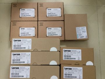
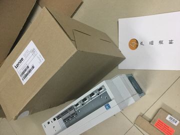
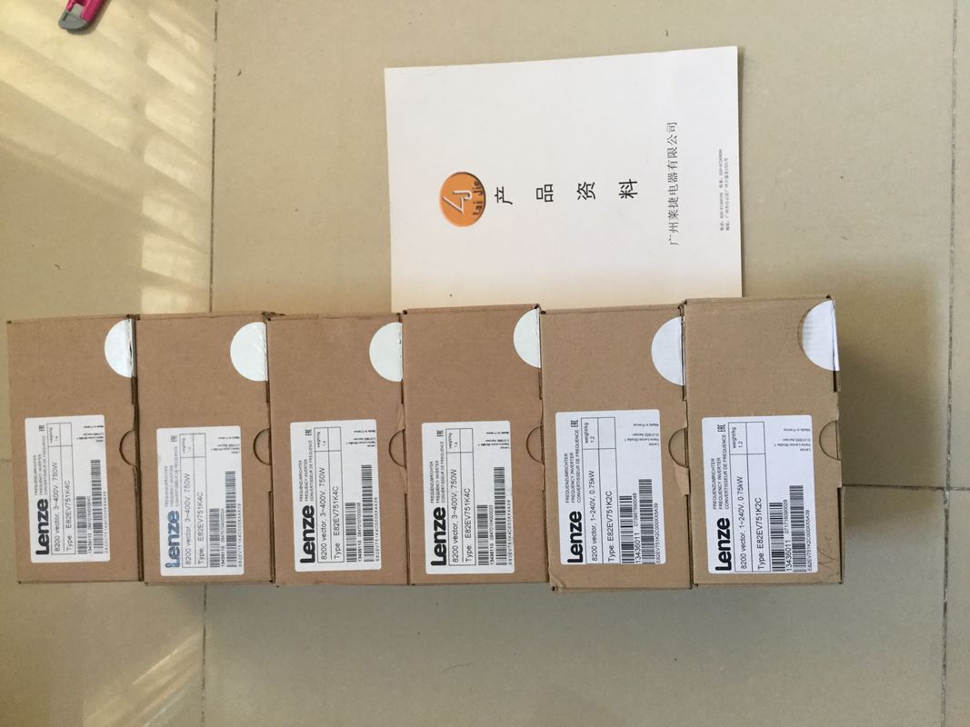
| Place of Origin: | GERMANY |
| Brand Name: | LENZE |
| Certification: | CE |
| Model Number: | EVS9323-ESV100 |
| Minimum Order Quantity: | 1pcs |
|---|---|
| Packaging Details: | carton |
| Delivery Time: | in stock |
| Payment Terms: | T/T, Western Union, MoneyGram |
| Supply Ability: | 100pcs/week |
| LENZE: | LENZE | Material: | Iron |
|---|---|---|---|
| Color: | Black | Temperature: | 20-90 |
| Dimension: | 90mm | Wire: | Wire |
| EVS9323-ESV100: | EVS9323-ESV100 | Germany: | Germany |
![]()
![]()
![]()
![]()
| Possible for voltage output typeThe compact CPU can generate a hardware interrupt for the following events: | |
| Below low limit 1 ● Above high limit 1 |
You can find detailed information on the event in the hardware interrupt organization block
with the "RALARM" (read additional interrupt information) instruction and in the STEP 7 (TIA
Portal) online help.
The start information of the organization block includes information on which channel of the
analog on-board I/O triggered the hardware interrupt. The figure below shows the
assignment to the bits of double word 8 in local data.
If the two high limits 1 and 2 are reached at the same time, the analog on-board I/O always
signals the hardware interrupt for high limit 1 first. The configured value for high limit 2 is
irrelevant. After processing the hardware interrupt for high limit 1, the compact CPU triggers
the hardware interrupt for high limit 2.
The analog on-board I/O behaves accordingly when the low limits are reached
simultaneously. If the two low limits 1 and 2 are reached at the same time, the analog onboard
I/O always signals the hardware interrupt for low limit 1 first. After processing the
hardware interrupt for low limit 1, the analog on-board I/O triggers the hardware interrupt for
low limit 2.A diagnostics alarm is output for each diagnostics event and the ERROR LED flashes on the
analog on-board I/O. The diagnostics alarms can, for example, be read out in the diagnostics
buffer of the CPU. You can evaluate the error codes with the user program.
Table 6- 11 Diagnostics alarms, their meaning and corrective measures
Diagnostics alarm Error code Meaning Remedy
Wire break 6H Resistance of encoder circuit too
high
Use a different encoder type or modify the
wiring, for example, using cables with
larger cross-section
Interruption of the cable between the
analog on-board I/O and sensor
Connect the cable
Channel not connected (open) ? Disable diagnostics
? Connect the channel
Overflow 7H Measuring range exceeded Check the measuring range
The output value set by the user
program exceeds the valid rated
range/overrange
Correct the output value
Underflow 8H Value below measuring range Check the measuring range
The output value set by the user
program is below the valid rated
range/underrange
Correct the output value
Short-circuit to ground 1H Overload at output Eliminate overload
Short-circuit of output QV to MANA Eliminate the short-circuitA diagnostics alarm is output for each diagnostics event and the ERROR LED flashes on the
digital on-board I/O. You can read out the diagnostics alarms, for example, in the diagnostics
buffer of the CPU. You can evaluate the error codes with the user programNo supply voltage L+ Feed supply voltage L+
Hardware interrupt
lost
16H The digital on-board I/O cannot trigger an
interrupt because the previous interrupt
was not acknowledged; possibly a configuration
error
? Change the interrupt processing in the
CPU and reconfigure the digital onboard
I/O.
Diagnostics interrupt when using high-speed counters
Table 6- 13 Diagnostics alarms, their meaning and corrective measures
Diagnostics alarm Error code Meaning Corrective measures
Illegal A/B signal
ratio
500H ? Time sequence of the A and B signals
of the incremental encoder do not
meet certain requirements
? Possible causes:
– Signal frequency too high
– Encoder is defective
– Process wiring is incorrect
? Correct the process wiring
? Check the encoder/sensor
? Check the parameter assignmentpt
The compact CPU can generate a hardware interrupt for the following events:
● Rising edge
● Falling edge
You will find detailed information on the event in the hardware interrupt organization block
with the "RALRM" (read additional interrupt information) instruction and in the STEP 7 online
help.
The start information of the organization block includes information on which channel
triggered the hardware interrupt. The figure below shows the assignment to the bits of
double word 8 in local datatriggers a hardware interrupt in the CPU.
Closing of the internal gate (gate stop) 2 When the internal gate is closed, the technology function
triggers a hardware interrupt in the CPU.
Overflow (high counting limit violated) 3 When the count value exceeds the high counting limit, the
technology function triggers a hardware interrupt in the
CPU.
Underflow (low counting limit violated) 4 When the count value falls below the low counting limit, the
technology function triggers a hardware interrupt in the