 |
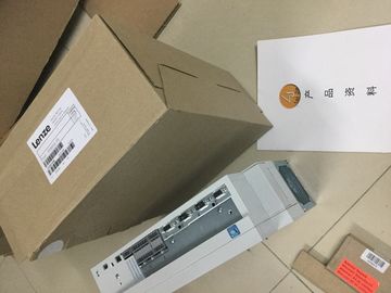
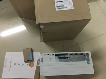
| Place of Origin: | GERMANY |
| Brand Name: | LENZE |
| Certification: | CE |
| Model Number: | EVF9330-EV |
| Minimum Order Quantity: | 1pcs |
|---|---|
| Packaging Details: | carton |
| Delivery Time: | in stock |
| Payment Terms: | T/T, Western Union, MoneyGram |
| Supply Ability: | 100pcs/week |
| LENZE: | LENZE | EVF9330-EV: | EVF9330-EV |
|---|---|---|---|
| GERMANY: | GERMANY | Mateial: | Iron |
| Color: | Black | Temperature: | 20-90 |
| Dimension: | 80mm |
![]()
![]()
![]()
![]()
| User sets MODE_SLOT to 1 • User sets LD_SLOT to the required value (1 for period duration) |
|
| User changes value in SLOT continuously and technology channel evaluates continuously | |
| Value in SLOT exceeds permitted limit, technology channel shows this ERR_SLOT_VAL and continues working |
with the last valid value
④ Value in SLOT again in permitted range, technology channel resets ERR_SLOT_VAL independently and continues
working with the value in SLOT
⑤ User resets LD_SLOT and MODE_SLOT, technology channel continues to work with last value
Figure 3-5 Cyclic updatingThe user program receives current values and status information from the pulse width
modulation via the feedback interface.
Feedback interface per channel
The following table shows the feedback interface assignment:The channel is correctly configured, is operating
and supplying valid data.
0: Not ready to run
1: Ready to run
STS_SW_ENABLE Current status of the software enable 0: SW_ENABLE is not active
1: SW_ENABLE detected
STS_LD_SLOT Acknowledgment bit for each action of the
SLOT in the SLOT mode for individual updating
(for a description of the acknowledgment
bit, refer to the section Handling the
SLOT parameter (control interface)
(Page 65)).
Each switching of this bit represents a successful
LD_SLOT action.
STS_ENABLE The output sequence is active.
(STS_ENABLE always depends on the
status of the software enable
STS_SW_ENABLE)
0: No output sequence running
1: Output sequence running
STS_DQA State of the pulse output (DQA) 0: Pulse output is not active
1: Pulse output is active
The connecting plug for the supply voltage is plugged in when the CPU ships from the
factory.
The following table shows the terminal assignment for a 24 V DC power supply.24 V DC of the supply voltage
② Ground of the supply voltage
③ Ground of the supply voltage for loop-through (maximum of 10 A permitted)
④ +24 V DC of the supply voltage for loop-through (maximum of 10 A permitted)
⑤ Spring-loaded NC contact (one spring-loaded NC contact per terminal)
Bridged internally:
① and ④
② and ③
Figure 4-1 Connection for supply voltage
If the CPU is supplied by a system power supply, it is not necessary to connect the 24 V
supply.The assignment corresponds to the Ethernet standard for an RJ45 plug.
● When autonegotiation is deactivated, the RJ45 socket is allocated as a switch (MDI-X).
● When autonegotiation is activated, autocrossing is in effect and the RJ45 socket is
allocated either as data terminal equipment (MDI) or a switch (MDI-X)The CPU 1511C-1 PN has a PROFINET interface with two ports. The PROFINET interface
itself has a MAC address, and each of the two PROFINET ports has its own MAC address.
The CPU 1511C-1 PN therefore has three MAC addresses in total.
The MAC addresses of the PROFINET ports are needed for the LLDP protocol, for example
for the neighborhood discovery function.
The number range of the MAC addresses is continuous. The first and last MAC address are
lasered on the rating plate on the right side of each CPU 1511C-1 PN.
The table below shows how the MAC addresses are assigned.
Table 4- 1 Assignment of the MAC addresses
Assignment Labeling
MAC address 1 PROFINET interface X1
(visible in STEP 7 for accessible devices)
• Front, lasered
• Right side, lasered
(start of number range)
MAC address 2 Port X1 P1 R (required for LLDP, for
example)
• Front and right side, not lasered
MAC address 3 Port X1 P2 R (required for LLDP, for
example)
• Front, not lasered
• Right side, lasered
(end of number range)You can use and combine the different wiring options for all channels. Note, however, that
unneeded terminals of an analog input channel must not be connectedThe following figure shows the terminal assignment for current measurement with 4-wire
measuring transducer at the channels available for this measurement type (channels 0 to 3).As an alternative to connecting a 4-wire measuring transducer, you can also connect 2-wire
measuring transducers to channels 0 to 3. An external 24 V power supply is required to
connect a 2-wire measuring transducer to the analog on-board I/O of the compact CPU.
Feed this voltage short-circuit proof to the 2-wire transducer. Use a fuse to protect the power
supply unit.
NOTICE
Defective measuring transducer
Note that the analog input of the measuring transducer is not protected against destruction
in the event of a defect (short circuit). Take the necessary precautions against such cases.
The figure below shows an example of the connection of a 2-wire measuring transducer to
channel 0 (CH0) of the analog on-board I/OThe following figure shows the terminal assignment for 4-wire connection of resistance-type
sensors or thermal resistors at the channel available for this (channel 4)Analog-to-digital converter (ADC)
② LED interface
③ Infeed element (for shielding only)
④ Digital-to-analog converter (DAC)
⑤ Equipotential bonding cable (optional)
⑥ 4-wire connection
Figure 4-6 Block diagram and terminal assignment for 4-wire connectionThe following figure shows the terminal assignment for 3-wire connection of resistance-type