 |
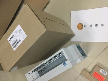
| Place of Origin: | GERMANY |
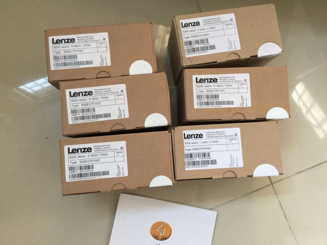
| Brand Name: | LENZE |
| Certification: | CE |
| Model Number: | EVF9325-EV 5.5kW |
| Minimum Order Quantity: | 1pcs |
|---|---|
| Packaging Details: | carton |
| Delivery Time: | in stock |
| Payment Terms: | T/T, Western Union, MoneyGram |
| Supply Ability: | 100pcs/week |
| LENZE: | LENZE | EVF9325-EV 5.5kW: | EVF9325-EV 5.5kW |
|---|---|---|---|
| GERMANY: | GERMANY | Temperature: | 20-90 |
| Material: | Iron | Color: | Black |
| Dimension: | 80mm |
![]()
![]() pulse output as high-speed
pulse output as high-speed
output. The requirement for this is![]()
| that the selected pulse output supports operation as high-speed output. |
|
| Deactivated The output supports frequencies of up to 10 kHz (load dependent) |
|
| and currents of up to 0.5 A or frequencies of up to 100 Hz and currents of up to 0.5 A depending |
on the performance capability of
the selected output.
Deactivated
Activated
The output supports frequencies
of up to 100 kHz and currents of
up to 0.1 A.Interprets the ratio value in the
field OUTPUT_VALUE" of the
control interface as 1/27648 of
the current period duration.
Supported value range from 0 to
27 648
1/100
1/100
Interprets the ratio value in the
field "OUTPUT_VALUE" of the
control interface as percentage
value of the current period duration.
Supported value range 0 to 100
1/1000
Interprets the ratio value in the
field "OUTPUT_VALUE"of the
control interface as a one-tenth
percentage point of the current
period duration.
Supported value range from 0 to
1 000
1/10000
Interprets the ratio value in the
field "OUTPUT_VALUE" of the
control interface as a onehundredth
percentage point of the
current period duration.
Supported value range from 0 to
10 000
Minimum pulse
duration
Defines the minimum pulse duration
and the minimum interpulse
period of the output signal of the
channel. The channel suppresses
all pulses and pauses that are
below the specified value.
0 μs to 10 000 000 μs (10 s) 0 μs
Period duration Defines the period duration of the
output signal of the channel in μs.
In RUN, the user program can
control the period duration via the
control and feedback interface of
the channel.
x to 10 000 000 μs (10 s)
at 100 kHz hardware output
(high-speed output (0.1 A) activated):
10 μs to 10 000 000 μs
(10 s)
at 10 kHz hardware output (highspeed
output (0.1 A) deactivated):
100 μs to 10 000 000 μs
(10 s)
at 100 kHz hardware output
(high-speed output (0.1 A) deactivated):
10 000 μs (10 ms) to
10 000 000 μs (10 sThe parameter "Pulse output
(DQA)" defines the hardware output
to use as pulse output channel.In this operating mode, you can assign a frequency value with high frequencies more
precisely than by using the period duration in PWM mode.
A rectangular signal with an assigned frequency and a constant on-load factor of 50% is
generated at the digital output.
The frequency output mode has the following functions:
● When the option "High-speed output (0.1 A)" is activated, you can generate a minimum
pulse duration of 2 μs at a current of 100 mA. If the option "High-speed output (0.1 A)" is
not activated, you can generate a minimum pulse duration of 20 μs with a load > 0.1 A
and a minimum pulse duration of 40 μs with a load of ≥ 2mA and a current of maximum
0.5 A.
If you use a standard output, you can generate a minimum pulse duration of 100 µs with
a load of > 0.1 A and a minimum pulse duration of 200 µs with a load of ≥ 2 mA and a
current of max. 0.5 A.For the frequency output mode, the user program directly accesses the control and feedback
interface of the channel.
Reconfiguration via the instructions WRREC/RDREC and parameter assignment data record
128 is supported. You can find additional information in section Parameter data records
(PWM) (Page 167).The control program must initiate the enable for the output sequence with the help of the
software enable (SW_ENABLE 0 → 1). The feedback bit STS_SW_ENABLE indicates that
the software enable is pending at the pulse generator.
If the software enable is activated (rising edge), STS_ENABLE is set. The output sequence
runs continuously, as long as SW_ENABLE is set.