 |
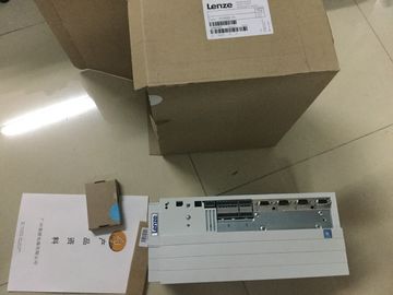
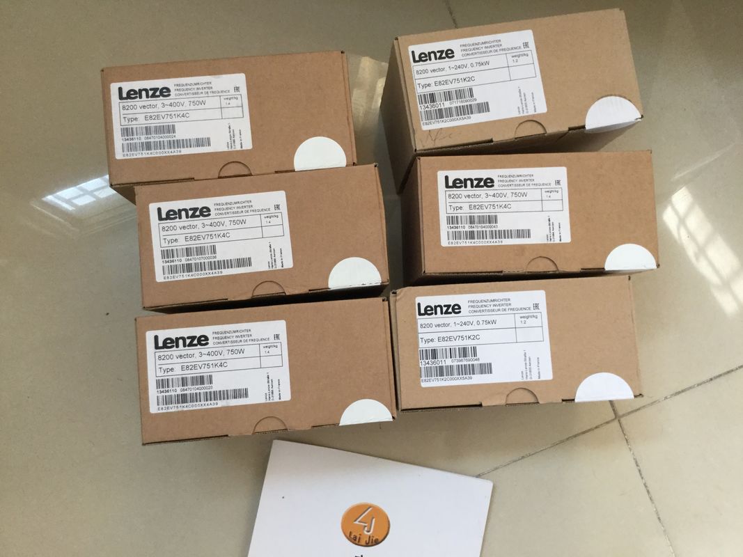
| Place of Origin: | GERMANY |
| Brand Name: | LENZE |
| Certification: | CE |
| Model Number: | EVF9326-EVV004 |
| Minimum Order Quantity: | 1pcs |
|---|---|
| Packaging Details: | carton |
| Delivery Time: | in stock |
| Payment Terms: | T/T, Western Union, MoneyGram |
| Supply Ability: | 100pcs/week |
| LENZE: | LENZE | EVF9326-EVV004: | EVF9326-EVV004 |
|---|---|---|---|
| GERMANY: | GERMANY | Material: | Iron |
| Color: | Black | Temperature: | 20-90 |
| Wire: | Wire | Dimension: | 90mm |
![]()
![]()
![]()
| No supply voltage L+ With the parameter "Missing supply voltage L+", |
|
| ou activate the diagnostic interrupt of the channel in the event of no supply voltage L+. |
|
| Deactivated Deactivated Activated Data exchange with |
he drive
Reference speed With the parameter "Reference
speed", you define
the reference value for the
drive velocity. The drive
velocity is defined as
percentage value of the
reference speed in the
range from -200% to
+200%.
Floating-point number:
1.0 to 20 000.0 (rpm)
3 000.0
(rpm)
Maximum speed The parameter "Maximum
speed" is used to define
the required maximum
speed for your application.
The supported value range depends on:
• the signal type selected under "Operating
mode"
• the value defined under "Increments per
revolution"
• the value defined under "Reference
speed"
The low limit of the value range is:
• for the signal type "PTO (A, B phaseshifted
- quadruple)": 0.1 Hz * 60 s/min *
4) / Increments per revolution
• for the non-quadruple PTO signal types:
(0.1 Hz * 60 s/min) / Increments per revolution
The high limit of the value range is the minimum
of the value:
• 2 * reference speed
and of the value:
• for the signal type "PTO (A, B phaseshifted
- quadruple)": (100 000 Hz *
60 s/min * 4) / Increments per revolution
• for the non-quadruple PTO signal types:
(100 000 Hz * 60 s/min) / Increments per
revolution
3 000.0
(rpm)
Increments per
revolution
The "Increments per revolution"
is used to define
the number of increments
per revolution (also in
microstep mode), which is
required by the drive for a
revolution.Bits in incr. actual
value
(G1_XIST1)
The parameter defines the
number of bits for the
coding of the fine resolution
in the current incremental
value of
G1_XIST1.
0 0
Stop behavior
Quick stop time The parameter "Quick
stop time" defines the time
period within which the
drive should go from the
maximum speed to a
standstill (OFF3).
1 to 65 535 (ms) 1 000 (ms)
Hardware
inputs/
outputs
Reference switch
input
The parameter "Reference
switch input" defines the
hardware input of the
reference switch.
[Input address of the reference switch DI] --
Edge selection
reference switch
The parameter "Edge
selection reference
switch" defines the edge
type which is to be detected
by the reference
switch.
Rising edge Rising edge
Falling edge
Measuring input The parameter "Measuring
input" defines thehardware input of themeasuring input.[Input address of the measuring input DI] --"Drive ready"inputThe parameter ""Driveready" input" defines thehardware input of theinput "Drive ready".[Input addresses of the inputs "Drive ready"
DIn]--Pulse output Afor "PTO (pulse(A) and directionB)"
The parameter "Pulseoutput A" defines thehardware output for PTOsignal A.[Output address DQ for PTO signal A (output
frequency 100 kHz)]
Grayed outRead onlyaccess tothe parameter
Direction outputBfor "PTO (pulse(A) and direction
B))"The parameter "Directionoutput B" defines the
hardware output for PTOsignal B.[Output address 1 of the DQ for PTO signal B
(output frequency 100 kHz)]Qn (outpufrequency100 kHz) [Output address 2 of the DQ for PTO signal B(output frequency 100 kHz)]