 |
| Place of Origin: | GERMANY |
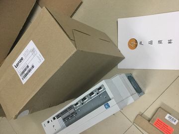
| Brand Name: | Lenze |
| Certification: | CE |
| Model Number: | EVS9322-EP |
| Minimum Order Quantity: | 1pcs |
|---|---|
| Packaging Details: | carton |
| Delivery Time: | in stock |
| Payment Terms: | T/T, Western Union, MoneyGram |
| Supply Ability: | 100pcs/week |
| LENZE: | LENZE | EVS9322-EP: | EVS9322-EP |
|---|---|---|---|
| GERMANY: | GERMANY | Material: | Iron |
| Color: | Black | Temperature: | 20-90 |
| Wire: | Wire |
![]()
![]()
![]()
![]()
| I/O (Page 162) Support of the value status |
|
| (Quality Information, QI) Value status = 1 ("Good") indicates that the process |
|
| value specified by the user program is correctly output at the terminal. |
Value status = 0 ("Bad") indicates that the process
value output at the hardware output is incorrect.
The digital on-board I/O module has 16 high-speed
inputs for signals up to a max. of 100 kHz. The inputs
can be used as standard inputs and as inputs for technology
functions.
The inputs have a rated input voltage of 24 V DC.
The inputs are suitable for switches and 2-/3-/4-wire
proximity switches.
Chapter Wiring (Page 79)
Configurable diagnostics The digital on-board I/O module is able to diagnose
errors. The module reports the diagnosed state to the
CPU using a diagnostics error interrupt. You can parameterize
the type of diagnostics channel-specifically.
Chapter Parameters of the digital
on-board I/O (Page 121)
Hardware interrupt You can react to process events (such as positive
edge, negative edge) through the configuration of a
hardware interrupt. Hardware interrupts can be parameterized
channel-granularly.
Chapter Parameters of the digital
on-board I/O (Page 121)
Chapter Structure of a data record
for input channels of the digital onboard
I/O (Page 171)
STEP 7 online helpThe digital on-board I/O module is able to diagnose
errors. The module reports the diagnosed state to the
CPU using a diagnostics error interrupt. You can parameterize
the type of diagnostics channel-specifically.
Chapter Interconnection overview of
the outputs (Page 109)
Standard and high-speed outputs
Standard outputs The digital on-board I/O module has 16 standard outputs.
Chapter Wiring (Page 79)
High-speed outputs Of the 16 standard outputs you can also use 8 outputs
as high-speed outputs for technology functions.
Rated output voltage The outputs have a rated output voltage of 24 V DC.
Output frequencies and
output currents
Rated output current as output for standard mode:
0.5 A per channel.
As an output for technology functions, you can select
between an output current of up to 0.5 A at an output
frequency up to 10 kHz (load dependent) and a reduced
output current of max. 0.1 A at an increased
output frequency of up to 100 kHz.
Chapter Interconnection overview of
the outputs (Page 109)
Application The outputs are suitable for, e.g. solenoid valves, DC
contactors and indicator lights, or also for signal transmission
or proportional valves.
Driver blocks with pushpull
outputs.
The digital outputs feature driver blocks with push-pull
outputs. Due to their basic functional design, such driver
blocks always contain parasitic diodes that act as
freewheeling diodes when shutting off inductive loads.
The shutdown voltage is limited to -0.8 V. Therefore,
the demagnetization of inductive loads takes longer and
can be approximately calculated using the following
formula.
tau = L / R (tau= time constant, L = inductance value,
R = ohmic resistance value)
After the expiration of a period of 5 * tau, the current
has decreased in effect to 0 A due to the inductive load.
The maximum value is derived from:
tau = 1.15H / 48 Ohm = 24 ms. After
5 * 24 ms = 120 ms, the current has decreased in effect
to 0 A.
For comparison: With standard modules, inductive
shutdown voltage is limited, for example, to Vcc -53 V
(supply voltage – 53 V), which causes the current to
decrease to 0 A after about 15 ms.
Figure "Current flow with correct
wiring using the digital on-board I/O
X11 as an example" in Chapter
Wiring and block diagrams of the
digital on-board I/O (Page 92).You can use technology and standard functions at the same time, provided the hardware
allows this. For example, all the digital inputs not assigned to the counting, measuring or
position detection or PTO technology functions can be used as standard DI.
Inputs to which technology functions are assigned can be read. Outputs to which technology
functions are assigned cannot be written.The high-speed digital inputs of the digital on-board
I/O module support technology functions such as fast
counting, measuring, position detection and pulse
generators (PWM, PTO and frequency output). Due
to the supported technology functions, the compact
CPUs are suitable for controlling pumps, fans, mixers,
conveyor belts, lifting platforms, gate control systems,
building management systems, synchronized axes,
etc.
Chapter Technology functions