 |
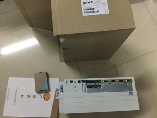
| Place of Origin: | GERMANY |
| Brand Name: | Lenze |
| Certification: | CE |
| Model Number: | EVS9322-EPV100 |
| Minimum Order Quantity: | 1pcs |
|---|---|
| Packaging Details: | carton |
| Delivery Time: | in stock |
| Payment Terms: | T/T, Western Union, MoneyGram |
| Supply Ability: | 100pcs/week |
| Lenze: | Lenze | EVS9322-EPV100: | EVS9322-EPV100 |
|---|---|---|---|
| GERMANY: | GERMANY | Material: | Iron |
| Temperature: | 20-90 | Wire: | Wire |
| Dimension: | 80mm |
![]()
![]()
![]()
![]()
![]()
![]()
![]()
![]()
| Reconfiguration in RUN You have the option of reassigning parameters for the digital on-board I/O module in RUN (for example, |
|
| values for input delay of individual channels can be modified without affecting the other channels). |
|
| Chapter Parameters of the digital on-board I/O (Page 121) |
Chapter Parameter assignment
and structure of the parameter
data records of the digital onboard
I/O (Page 170)
Support of the value status
(Quality Information, QI)
Value status = 1 ("Good") indicates that the value of
the assigned input at the terminal is valid.
Value status = 0 ("Bad") indicates that no/too little
supply voltage L+ is applied at the terminal and that
the read value is therefore not valid.
Chapter Address space of the digital
on-board I/O (Page 113)The high-speed digital outputs of the digital on-board
I/O module support technology functions such as fast
counting, measuring, position detection and pulse
generators (PWM, PTO and frequency output). Due
to the supported technology functions, the compact
CPUs are suitable for controlling pumps, fans, mixers,
conveyor belts, lifting platforms, gate control systems,
building management systems, synchronized axes,
etc.
Chapter Technology functions
(Page 42)
Reconfiguration in RUN You have the option of reassigning parameters for the
digital on-board I/O module in RUN (for example,
behavior during CPU STOP, without affecting the
other channels).
• Chapter Parameters of the digital
on-board I/O (Page 121)
• Chapter Parameter assignment
and structure of the parameter
data records of the digital onboard
I/O (Page 170)
Support of the value status
(Quality Information, QI)
Value status = 1 ("Good") indicates that the process
value specified by the user program is correctly output
at the terminal.
Value status = 0 ("Bad") indicates that the process
value output at the hardware output is incorrect or the
channel is used for technology functions.
Chapter Address space of the digital
on-board I/O (Page 113)Chapter Address space of the
LEDs for the current operating mode and diagnostics status of the CPU
② Status and error displays RUN/ERROR of the analog on-board I/O
③ Status and error displays RUN/ERROR of the digital on-board I/O
④ Control keys
⑤ Display
Figure 2-4 View of the CPU 1511C-1 PN with closed front panels (front)
Note
Temperature range for display
To increase its service life, the display switches off at a temperature below the permitted
operating temperature of the device. When the display cools down again, it automatically
switches itself on again. When the display is switched off, the LEDs continue to show the
status of the CPU.
You can find additional information on the temperatures at which the display switches itself
on and off in the Technical specifications (Page 137).If you pull or plug the front panel of an automation system during operation,
personal injury or damage to property can occur in zone 2 hazardous areas.
Before you pull or plug the front panel in hazardous area zone 2, always ensure that the
automation system is de-energized. The CPU maintains its operating mode.
Locking the front panel
You can lock the front panel to protect your CPU against unauthorized access.
You can attach a security seal or a padlock with a hoop diameter of 3 mm to the front panelIn addition to the mechanical lock, you can also block access to a password-protected CPU
on the display (local lock) and assign a password for the display. For more information on
the display, the configurable protection levels and the local lock, refer to the ,
ET 200MPont view of the CPU without front panel and view from below
The following figure shows the operator control and connection elements of the
CPU 1511C-1 PN with the front cover of the CPU open① LEDs for the current operating mode and diagnostics status of the CPU
② Status and error displays RUN/ERROR of the analog on-board I/O
③ Status and error displays RUN/ERROR of the digital on-board I/O
④ Connector for power supply
⑤ Operating modes with "STOP ACTIVE" LED
⑥ LEDs for the 2 ports (X1 P1 and X1 P2) of the PROFINET interface X1
⑦ MAC address
⑧ Display
Figure 2-6 View of the CPU 1511C-1 PN without front panel on the CPU (front)Shield contact surfaces
② Plug-in connection for power supply