|
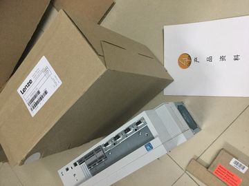
| Place of Origin: | GERMANY |
| Brand Name: | LENZE |
| Certification: | CE |
| Model Number: | E94ASSE0074 |
| Minimum Order Quantity: | 1pcs |
|---|---|
| Packaging Details: | carton |
| Delivery Time: | in stock |
| Payment Terms: | T/T, Western Union, MoneyGram |
| Supply Ability: | 100pcs/week |
| LENZE: | LENZE | E94ASSE0074: | E94ASSE0074 |
|---|---|---|---|
| GERMANY: | GERMANY | Material: | Iron |
| Color: | Black | Temperature: | 20-90 |
| Dimension: | 80mm |
![]()
![]()
![]()
![]()
| case of no supply voltage L+ Deactivated Deactivated |
|
| ctivated Parameter High-speed output |
|
| ctivated Parameter High-speed output |
whether you want to use the selected
pulse output as high-speed
output. The requirement for this is
that the selected pulse output
supports operation as high-speed
output.
Deactivated
The output supports frequencies
of up to 10 kHz (load dependent)
and currents of up to 0.5 A or
frequencies of up to 100 Hz and
currents of up to 0.5 A depending
on the performance capability of
the selected output.
Deactivated
Activated
The output supports frequencies
of up to 100 kHz and currents of
up to 0.1 A.
Output format Defines the value for the frequency
output in the field
"OUTPUT_VALUE" of the control
interface of the channel.
1 Hz
Interprets the value of the frequency
output in the field
"OUTPUT_VALUE" as frequency
with the unit Hz.
1 Hz
Hardware
inputs/
outputs
Pulse output
(DQA)
The parameter "Pulse output
(DQA)" is used to define the hardware
output that you want to use
as pulse output channel.
For B:
X11, terminal 21 (DQ0 / %Q4.0):
10 kHz / 0.5 A or 100 kHz / 0.1 A
Hardware
output with
the least
significant
address For B:
X11, terminal 31 (DQ8 / %Q5.0):
100 Hz / 0.5 A
Output signals for frequency output mode
Output signal Meaning Value range
Continuous pulse current at the digital
output PWM DQA
A pulse for the assigned frequency is output
at the digital output PWM DQA.
Continuous pulse currentperating mode: PTO
The PTO (Pulse Train Output) mode can be used to output position information. This allows
you to, for example, control stepper motor drives or simulate an incremental encoder. The
frequency of the pulses represents the speed, while the number of pulses represents the
distance. The direction can also be specified by using two signals per channel. You can use
a PTO channel for setpoint output (drive) for an axis technology object.
PTO mode is divided into the following four signal types:
● PTO (pulse (A) and direction (B)): If you select the PTO signal type (pulse (A) and
direction (B)), an output (A) controls the pulses and an output (B) controls the direction. B
is 'High' (active) when pulses are generated in a negative direction. B is 'Low' (inactive)
when pulses are generated in a positive direction.TO (Count up (A) and Count down (B)): When you select the PTO signal type (count up
(A) and count down (B)), an output (A) outputs pulses for positive directions and another
output (B) outputs pulses for negative directions.PTO (A, B phase-shifted): When you select the PTO signal type (A, B phase-shifted), the
two outputs pulses with the specified velocity, but phase-shifted by 90 degrees. This is a
1x combination in which the pulse shows the duration between two positive transitions of
A. In this case, the direction is determined based on the output which first changes from 0
to 1. With positive direction, A precedes B. With negative direction B precedes A.
The number of generated pulses is based on the number of 0-to-1 transitions from phase
A. The phase ratio determines the direction of motion:
PTO (A, B phase-shifted - quadruple): When you select the PTO signal type (A, B phaseshifted,
quadruple), the two outputs transmit pulses with the specified velocity, but phaseshifted
by 90 degrees. The quadruple signal type is a 4x configuration in which each edge
transition corresponds to an increment. Therefore, a full period of the signal A contains
four increments. In this way, two outputs, each with 100 kHz signal frequency, can be
used to output a control signal that supplies 400 000 increments per second. The
direction is determined based on the output which first changes from 0 to 1. With positive
direction, A precedes B. With negative direction B precedes A.No supply voltage
L+
With the parameter "Missing
supply voltage L+",
you activate the diagnostic
interrupt of the channel in
the event of no supply
voltage L+.
Deactivated Deactivated
Activated
Data exchange
with
the drive
Reference speed With the parameter "Reference
speed", you define
the reference value for the
drive velocity. The drive
velocity is defined as
percentage value of the
reference speed in the
range from -200% to
+200%.
Floating-point number:
1.0 to 20 000.0 (rpm)
3 000.0