|
| Place of Origin: | GERMANY |
| Brand Name: | LENZE |
| Certification: | CE |
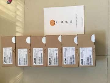
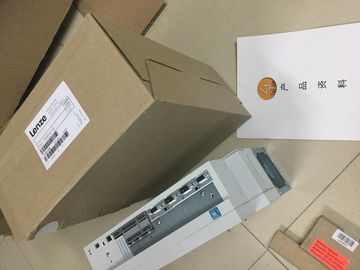
| Model Number: | E94ASSE1454 |
| Minimum Order Quantity: | 1pcs |
|---|---|
| Packaging Details: | carton |
| Delivery Time: | in stock |
| Payment Terms: | T/T, Western Union, MoneyGram |
| Supply Ability: | 100pcs/week |
| LENZE: | LENZE | E94ASSE1454: | E94ASSE1454 |
|---|---|---|---|
| Material: | Iron | Color: | Black |
| Temperature: | 20-90 | Dimension: | 80mm |
| Wire: | Wire | Germany: | Germany |
![]()
![]()
![]()
![]()
| diagnostics option. You activate the use of the value status in the hardware configuration of | When you activate the value status, the input area of the digital on-board I/O (X11/X12) contains four additional bytes, |
| STEP 7 (TIA Portal). Value status is deactivated by default. You can activate/deactivate the | which provide the QI bits to the 16 digital input channels and 16 digital output channels. You access the QI bits through the user program. Value status of input channels |
| alue status of the digital on-board I/O for X11 and X12 independently of each other. | Value status = 1 ("Good") indicates that the value of the assigned input at the terminal is valid |
Value status = 0 ("Bad") indicates that no or too little supply voltage L+ is applied at the
terminal and that the read value is therefore not valid.
Value status of output channels
The value status = 1 ("Good") indicates that the process value specified by the user program
is correctly output at the terminal.
The value status = 0 ("Bad") indicates that the process value output at the hardware output is
incorrect or the channel is used for technology functions.
Possible cause for value status = 0:
● The supply voltage L+ is missing at the terminals or is not sufficient
● Outputs are inactive (for example, CPU in STOP)
● Technology functions (HSC, PWM or PTO) use the channel
Note
Behavior of the value status at the output channels for technology functions
The output channels return the value status 0 ("Bad") when a technology channel (HSC,
PWM or PTO) is used. It does not matter in this context whether the output value is incorrect
or noYou can find a descrtion of the control interface in the section Assignment of the control
interface of the high-speed counters (Page 41). You can find a descrtion of the feedback
interface in the section Assignment of the feedback interface of the high-speed counters
(Page 43).The analog on-board I/O is set to voltage measurement type and measuring range ±10 V by
default for the inputs on channels 0 to 3. By default, channel 4 is set to resistance measuring
type and measuring range 600 Ω. If you want to use another measurement type or
measuring range, change the parameter settings of the analog on-board I/O with STEP 7
(TIA Portal).
Disable unused inputs to prevent disturbances that cause incorrect behavior (e.g. triggering
of a hardware interrupt).The analog on-board I/O is set to voltage output type and output range ±10 V as default for
the outputs. If you want to use another output range or output type, you need to change the
parameter settings of the analog on-board I/O with STEP 7 (TIA Portal).
Output types and output ranges
The following table shows the output type and the corresponding output ranges.
Table 5- 4 Output type and output rangesYou specify the properties of the analog on-board I/O during parameter assignment with
STEP 7 (TIA Portal). The tables below list the parameters that can be set for inputs and
outputs, respectively.
When parameters are assigned in the user program, they are transferred to the analog onboard
I/O via data records with the WRREC instruction, see section Parameter assignment
and structure of the parameter data records of the analog on-board I/O (Page 148)All parameters can be set for on a channel-specific basis
2) Kelvin (K) is only possible for the "Standard range" measuring range and not for the "Climatic range" measuring range