 |
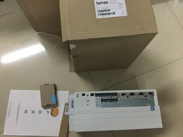
| Place of Origin: | GERMANY |
| Brand Name: | LENZE |
| Certification: | CE |
| Model Number: | E94ASSE0324 |
| Minimum Order Quantity: | 1pcs |
|---|---|
| Packaging Details: | carton |
| Delivery Time: | in stock |
| Payment Terms: | T/T, Western Union, MoneyGram |
| Supply Ability: | 100pcs/week |
| LENZE: | LENZE | E94ASSE0324: | E94ASSE0324 |
|---|---|---|---|
| GERMANY: | GERMANY | Material: | Iron |
| Color: | Black | Temperature: | 20-90 |
| Dimension: | 80mm |
![]()
![]()
![]()
![]()
| vindependently and continues working with the value in SLOT |
STS_ENABLE The output sequence is active. (STS_ENABLE always depends on the status of the software enable |
| User resets LD_SLOT and MODE_SLOT, technology channel continues to work with last value Figure 3-5 Cyclic updatingmodulation via the feedback interface. |
LOT in the SLOT mode for individual updating (for a descrtion of the acknowledgment bit, refer to the section Handling the |
| Feedback interface per channel The following table shows the feedback interface assAcknowledgment bit for each action of the |
SLOT parameter (control interface) (Page 65)). Each switching of this bit represents a successful LD_SLOT action. |
STS_SW_ENABLE)
0: No output sequence running
1: Output sequence running
STS_DQA State of the pulse output (DQA) 0: Pulse output is not active
1: Pulse output is active
+24 V DC of the supply voltage
② Ground of the supply voltage
③ Ground of the supply voltage for loop-through (maximum of 10 A permitted)
④ +24 V DC of the supply voltage for loop-through (maximum of 10 A permitted)
⑤ Spring-loaded NC contact (one spring-loaded NC contact per terminal)
Bridged internally:
① and ④
② and ③
Figure 4-1 Connection for supply voltage
If the CPU is supplied by a system power supply, it is not necessary to connect the 24 V
supplyhe assignment corresponds to the Ethernet standard for an RJ45 plug.
● When autonegotiation is deactivated, the RJ45 socket is allocated as a switch (MDI-X).
● When autonegotiation is activated, autocrossing is in effect and the RJ45 socket is
allocated either as data terminal equment (MDI) or a switch (MDI-X).The CPU 1511C-1 PN has a PROFINET interface with two ports. The PROFINET interface
itself has a MAC address, and each of the two PROFINET ports has its own MAC address.
The CPU 1511C-1 PN therefore has three MAC addresses in total.
The MAC addresses of the PROFINET ports are needed for the LLDP protocol, for example
for the neighborhood discovery function.
The number range of the MAC addresses is continuous. The first and last MAC address are
lasered on the rating plate on the right side of each CPU 1511C-1 PN.
The table below shows how the MAC addresses are assigned.
Table 4- 1 Assignment of the MAC addressesVoltage input channel n (voltage only)
Mn+/Mn- Measuring input channel n (only resistance-type transmitters or thermal
resistors (RTD))
In+/In- Current input channel n (current only)
Ic n+/Ic n- Current output for RTD, channel n
QVn Voltage output channel
QIn Current output channel
MANA Reference potential of the analog circuit
CHx Channel or display of the channel status
Infeed element
The infeed element is inserted on the front connector and serves to shield the analog onboard
I/O.
Note
The analog on-board I/O does not require power to be supplied by the infeed element. The
infeed element is, however, necessary for shielding.The following figure shows the terminal assignment for voltage measurement at the channels
available for this measurement type (channels 0 to 3)Analog-to-digital converter (ADC)
② LED interface
③ Infeed element (for shielding only)
④ Digital-to-analog converter (DAC)
⑤ Equotential bonding cable (optional)
⑥ Connector 4-wire measuring transducer
Figure 4-4 Block diagram and terminal assignment for current measurement with 4-wire measuring
transducerAs an alternative to connecting a 4-wire measuring transducer, you can also connect 2-wire
measuring transducers to channels 0 to 3. An external 24 V power supply is required to
connect a 2-wire measuring transducer to the analog on-board I/O of the compact CPU.
Feed this voltage short-circuit proof to the 2-wire transducer. Use a fuse to protect the power
supply unit.
NOTICE
Defective measuring transducer
Note that the analog input of the measuring transducer is not protected against destruction
in the event of a defect (short circuit). Take the necessary precautions against such cases.
The figure below shows an example of the connection of a 2-wire measuring transducer to
channel 0 (CH0) of the analog on-board I/O.ensor (e.g. pressure gauge)
② 2-wire measuring transducer
③ Fuse
④ Equotential bonding cable (optional)
Figure 4-5 2-wire measuring transducer at channel 0
Use the measurement type "Current (4-wire transducer)" and the measuring range
4 to 20 mA for the parameter assignment of the 2-wire measuring transducer in STEP 7
(TIA Portal).The following figure shows the terminal assignment for 3-wire connection of