 |
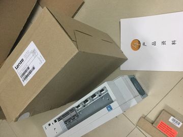
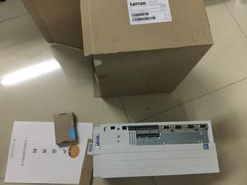
| Place of Origin: | GERMANY |
| Brand Name: | LENZE |
| Certification: | CE |
| Model Number: | E94ASSE0024 |
| Minimum Order Quantity: | 1pcs |
|---|---|
| Packaging Details: | carton |
| Delivery Time: | in stock |
| Payment Terms: | T/T, Western Union, MoneyGram |
| Supply Ability: | 100pcs/week |
| LENZE: | LENZE | E94ASSE0024: | E94ASSE0024 |
|---|---|---|---|
| GERMANY: | GERMANY | Color: | Black |
| Temperature: | 20-90 | Wire: | Wire |
| Dimension: | 80mm | Material: | Iron |
![]()
![]()
![]()
![]()
| Rising or falling edge of a digital input | Comparison values The integrated counter supports 2 comparison values and digital output HSC DQ1 |
| Rising edge of signal N at the encoder input | f the counter or measured value meets the set comparison condition, HSC DQ1 can be set in order to trigger direct control operations in the process. |
| Rising edge of signal N at the encoder input depending on the level of the assigned digital input |
Both comparison values can be set in the parameters and can be changed during runtime via the user program. |
Hardware interrupts
If you have enabled a hardware interrupt in the hardware configuration, the counter can
trigger a hardware interrupt in the CPU when a comparison event occurs, if there is overflow
or underflow, at a zero crossing of the counter, and/or at a change of count direction
(direction reversal). You can specify which events are to trigger a hardware interrupt during
operation in the hardware configuration.You configure the high-speed counters (HSC) in STEP 7 (TIA Portal).
The functions are controlled via the user program.
Reference
A detailed descrtion of configuring the counting and measuring functions can be found in:
● , ET 200MP, ET 200SP Counting, measurement and position detection in the STEP 7 online help under "Using technology functions > Motion Control > Motion
Control ()"
The High_Speed_Counter technology object is available for high-speed counting mode. We
therefore recommend use of the High_Speed_Counter technology object instead of the
control interface/feedback interface for controlling the high speed counter.
For information on configuring the technology object and programming the associated
instruction, refer to the , ET 200MP, ET 200SP Counting, measurement and position With pulse width modulation, a signal with defined cycle duration and variable on-load factor
is output at the digital output. The on-load factor is the relationsh of the pulse duration to
the cycle duration. In PWM mode, you can control the on-load factor and the cycle duration.
With pulse width modulation, you vary the mean value of the output voltage. Depending on
the connected load, you can control the load current or the power with this.
You can specify the pulse duration as one-hundredth of the period duration (0 to 100), as
one-thousandth (0 to 1 000), as one ten-thousandth (0 to 10 000) or in S7 analog format.Period duration
② Pulse duration
The pulse duration can be between 0 (no pulse, always off) and full scale (no pulse, period
duration always on).
The PWM output can, for example, be used to control the speed of a motor from standstill to
full speed or you can use it to control the position of a valve from closed to completely open.
You configure the pulse width modulation (PWM) mode in STEP 7 (TIA Portal).
The pulse width modulation mode has the following functions:
● When the option "High-speed output (0.1 A)" is activated, you can generate a minimum
pulse duration of 2 μs at a current of 100 mA. If the option "High-speed output (0.1 A)" is
not activated, you can generate a minimum pulse duration of 20 μs with a load > 0.1 A
and a minimum pulse duration of 40 μs with a load of ≥ 2 mA and a current of maximum
0.5 A. If a standard output is used, you can generate a minimum pulse duration of 100 μs
with a load of > 0.1 and a minimum pulse duration of 200 μs with a load of ≥ 2 mA.
● You can control the pulse output (DQA) of the channel manually via the control and
feedback interface.
● You can configure the reaction to CPU STOP. Upon change to CPU STOP, the pulse
output (DQA) is set to the configured state.For the pulse width modulation (PWM) mode, the user program directly accesses the control
and feedback interface of the channel.
Reconfiguration via the instructions WRREC/RDREC and parameter assignment data record
128 is supported. You can find additional information in section Parameter data records
(PWM) (Page 167).
You control the on-load factor (pulse-cycle ratio) of the pulse width via the OUTPUT_VALUE
field of the control interface. Pulse width modulation generates continuous pulses based on
this value. The period duration is adjustable.
The control program must output the enable for the output sequence with the help of the
software enable (SW_ENABLE 0 → 1). The feedback bit STS_SW_ENABLE indicates that
the software enable is pending at the PWM.
If the software enable is activated (rising edge), STS_ENABLE is set. The output sequence
runs continuously, as long as SW_ENABLE is set.
Note
Output control signal TM_CTRL_DQ
? If TM_CTRL_DQ = 1, the technology function takes over the control and generates pulse
sequences at the output PWM DQA.
? If TM_CTRL_DQ = 0, the user program takes over the control and the user can set the
output PWM DQA directly via the control bit SET_DQA.Deactivating the software enable (SW_ENABLE = 1 → 0) cancels the current output
sequence. The last period duration is not completed. STS_ENABLE and the digital output
PWM DQA are immediately reset to 0.