 |
| Place of Origin: | GERMANY |
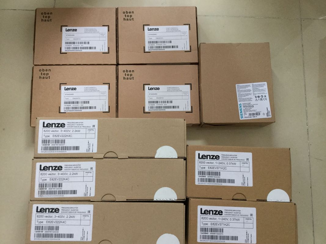
| Brand Name: | LENZE |
| Certification: | CE |
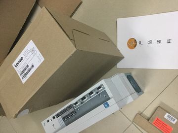
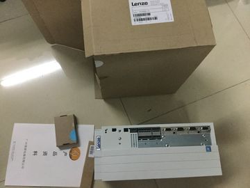
| Model Number: | E82EV903K4B201 |
| Minimum Order Quantity: | 1pcs |
|---|---|
| Packaging Details: | carton |
| Delivery Time: | in stock |
| Payment Terms: | T/T, Western Union, MoneyGram |
| Supply Ability: | 100pcs/week |
| LENZE: | LENZE | E82EV903K4B201: | E82EV903K4B201 |
|---|---|---|---|
| Material: | Iron | Color: | Black |
| Germany: | Germany | Temperature: | 20-90 |
| Dimension: | 90mm |
![]()
![]()
![]()
![]()
| In this section, we will explain the relationshs between the individual project components of the sample project. |
APPROVED for use in Class I, Division 2, Group A, B, C, D Tx; Class I, Zone 2, Group IIC Tx Installation Instructions for FM |
| ou will carry out the necessary configuration steps yourself at a later point in time. ● ANSI/ISA 82.02.01 (IEC 61010-1) |
WARNING - Explosion Hazard - Do not disconnect while circuit is live unless area is known to be non-hazardous. |
| CSA C22.2 No. 213 ● CSA 22.2 No. 1010.1 |
WARNING - Explosion Hazard - Substitution of components may impair suitability for Class I, Division 2 or Zone 2. |
This equment is suitable for use in Class I, Division 2, Groups A, B, C, D; Class I, Zone
2, Group IIC; or non-hazardous locations.
WARNING: EXPOSURE TO SOME CHEMICALS MAY DEGRADE THE SEALING
PROPERTIES OF MATERIALS USED IN THE RELAYS.emains in STOP.
Service data transfer is complete when the STOP LED stops flashing and is lit continuously.
If service data transfer has been successful, only the STOP LED lights up.
In the event of errors in transfer, the STOP LED is lit continuously and the ERROR LED
flashes. The CPU also stores a text file with a note on the error that occurred in the
DUMP.S7S folder
When the required color mixture is selected in the HMI screen "Reces", the values
are displayed in the CMYK color space by means of a bar diagram.
The color mixture can be shown with an additional display. This requires the
"Recescreen" scrt to be run.
③ You run the "Recescreen" scrt by clicking the "Display RGB Value" button. The
scrt assigns the RGB value assigned to the CMYK value to the display, because
CMYK values cannot be output directly on screens.
④ The required RGB value is calculated by the "SCL_Convert_CMYK_TO_RGB"
program blockThe "Fill rece" button starts the filling of the color components in the HMI screen "Start screen". The
button activates the "LAD_Control_Color_Valves" program block.
② The program block calculates how long each of the four valves needs to stay open for the color mixture
based on the specified rece and the number of tins that have to be filled.
③ LEDs below the tanks indicate that the valves are opened.
④ The "LAD_Tanks_Filling_Level" program block is executed at the same time as the filling. The program
block calculates the quantity remaining in the tank for the tank fill level. The fill levels of the tanks are
stored in the global data block "Filling".
he fill level indicators in the HMI screen are directly linked with the global data block and are updated
with each runtime acquisition cycleThe "Start mixing process" button starts the mixer of the color mixing plant in the HMI
screen "Start screen".
② The "LAD_Mixer" program block is called for this purpose at the CPU end. It activates
the mixer for three seconds.
③ The activation of the mixer is indicated by flashing in the HMI screenThe "Fill Color Mixture" button starts the filling of the tins in the HMI screen "Start
screen".
② The "SCL_Valve_Conveyor" program block is activated for this purpose at the CPU
end; it controls the valves and the conveyor belt.
③ The tins are animated according to the movement of the conveyor belt in the HMI
screen.
④ A counter indicates the number of tins that have already been filled.There is a button to reset the fill level of each of the four color tanks in the HMI screen
"Start screen".
② The reset of the respective fill level has been implemented in the "Main" program
block in networks 6 to 9.
③ Networks 6 to 9 reset the values to the Start value in the global data block "FillingThe new SIMATIC controller family with the Totally Integrated Automation Portal
(TIA Portal) offers you numerous new options to further increase the productivity of your
machines and to make the engineering process even more efficient. Explore the options in
this Getting Started.
In the first basic steps, you will get to know the new hardware better. We will also show you
how to configure and program the SIMATIC with SIMATIC STEP 7 V13
(TIA Portal). The connection of a SIMATIC HMI Comfort Panel with SIMATIC WinCC
Advanced V13 (TIA Portal) or SIMATIC WinCC Professional V13 (TIA Portal) completes the