 |
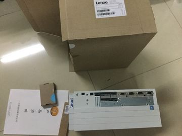
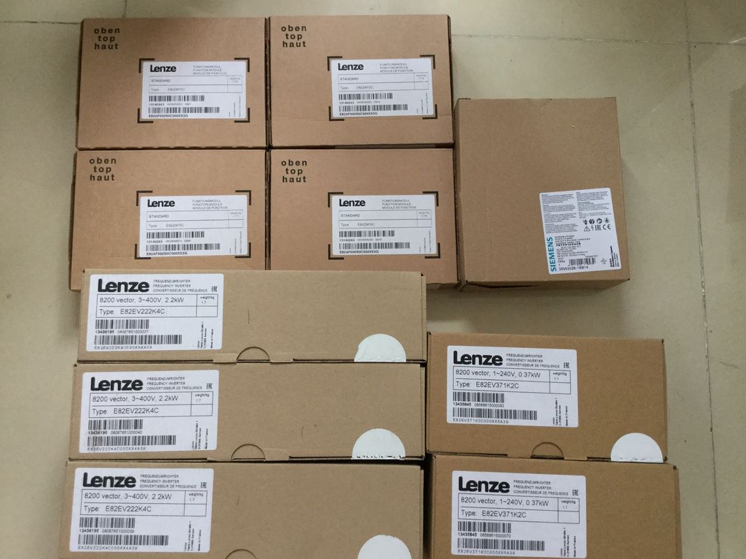
| Place of Origin: | GERMANY |
| Brand Name: | LENZE |
| Certification: | CE |
| Model Number: | E84AV-BDE3714SX0 |
| Minimum Order Quantity: | 1pcs |
|---|---|
| Packaging Details: | carton |
| Delivery Time: | in stock |
| Payment Terms: | T/T, Western Union, MoneyGram |
| Supply Ability: | 100pcs/week |
| LENZE: | LENZE | E84AV-BDE3714SX0: | E84AV-BDE3714SX0 |
|---|---|---|---|
| Germany: | Germany | Material: | Iron |
| Color: | Black | Temperature: | 20-90 |
| Wire: | Wire | Dimension: | 80mm |
![]()
![]()
![]()
| TEP 7 assigns default values for the minimum and maximum cycle times. | setting). For the tunnel application, assign synchronization modules for cables up to 10 km in length (6ES7960-1FB00-0AA5) to the H-CPUs as follows: |
| Select the minimum scan cycle time so that the cyclic program does not have to be executed more |
1. Change to the device view of an H-CPU. |
| frequently than your process requires.In STEP 7 synchronization modules for 10 m length are assigned to the H-CPUs (default | From the hardware catalog, drag and drop the synchronization module with the article number 6ES7960-1FB00-0AA5 to the interface for a synchronization module of the HCP |
The "Replace device- Synchronization module" dialog opens. Confirm the replacement
with "OK".The default values are displayed in the "Cycle" area of the CPU properties.
1. Set a maximum cycle time of 6000 ms and a minimum cycle time of 10 ms for the
example.
2. Adopt the presets for the other parameters.When you change the parameters described above for a CPU, the parameters are
automatically adopted in STEP 7 for the other CPU of the redundant system.In the H redundant system the devices communicate in a PROFINET ring via MRP.
Define the media redundancy role of the devices.
Assign the I/O modules for the various automation tasks in the three tunnel sections to the
three ET 200SP distributed I/O systems.
Set the watchdog time for each ET 200SP. If you set a higher watchdog time, then a failure
of the IO device on interruption of the PROFINET ring can be avoided.
Defining MRP role for ET 200SP in the PROFINET ring
Proceed as follows to define the media redundancy role for the ET 200SP distributed I/O
systems as devices in the ring:
1. In the network view of STEP 7, select PROFINET interface X1 of one of the two CPUs.
2. In the Inspector window, navigate to "Properties" > "General" > "Advanced options" >
"Media redundancy". 3. Click the "Domain settings" button.In the Inspector window, STEP 7 displays the properties of the MRP domain in which
PROFINET interface X1 of the CPU is located. The CPU has the role "Manager (auto)" in
a redundant system.
5. In the "MRP role" column of the "Devices" table, assign the MRP role "Client" to all other
deviceChange to the device view of an IM 155-6 PN HF.
2. In the properties of the interface module in the "General" area, assign "Section1" as the
name for tunnel section 1.
3. Select the following modules in succession from the hardware catalog. Assign the
modules to the interface module from slot 1 to 6:
– DQ 4x24VDC/2A ST (for traffic lights)
– DQ 4x24VDC/2A ST (for barrier)
– AI 4xU/I 2-wire ST (for outdoor light, indoor light and air-quality sensors)
– DQ 4x24VDC/2A ST (for fans)
– DQ 4x24..230VAC/2A HF (for tunnel lighting)
– 1 server module (as termination of the configuration)Assigning ET 200SP I/O modules
4. Double-click on the 3rd module DQ 4x24VDC/2A ST in the configuration (for fan).
5. In the module properties "General" > "Potential group", select "Enable new potential
group (light-colored BaseUnit)".
6. Double-click on the module DQ 4x24..230VAC/2A HF (for tunnel lighting).
7. In the module properties "General" > "Potential group", select "Enable new potential
group (light-colored BaseUnit)".
8. Double-click on the module AI 4xU/I 2-wire ST. In the module properties, set the measurement type "Voltage" and measuring range
"0..10 V" under "Inputs" for channels 0 to 2 in each case.
Setting the measurement type and measuring ranges
10.Set the measurement type to "Disabled" for channel 3.