 |
| Place of Origin: | Germany |
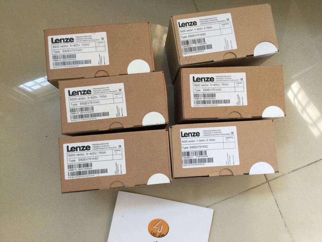
| Brand Name: | LENZE |
| Certification: | CE |
| Model Number: | E82EV152k4B |
| Minimum Order Quantity: | 1pcs |
|---|---|
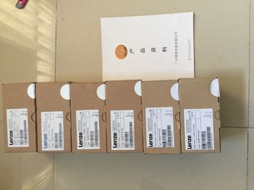
| Packaging Details: | carton |
| Delivery Time: | in stock |
| Payment Terms: | T/T, Western Union, MoneyGram |
| Supply Ability: | 100pcs/week |
| LENZE: | LENZE | E82EV152k4B: | E82EV152k4B |
|---|---|---|---|
| Germany: | Germany | Material: | Iron |
| Color: | Black | Temperature: | 20-90 |
| Dimension: | 80mm | Wire: | Wire |
![]()
![]()
![]()
![]()
| cables are protected against unauthorized access, e.g. by spatial access protectionInformation is provided below on the overall configuration of an R/H redundant | |
| system on a grounded incoming supply (TN-S network). The specific subjects discussed are: ● Shut-off devices, short circuit and overload protection in accordance with |
|
| IEC 60364, corresponds to DIN VDE 0100 – IEC 60204, corresponds to DIN VDE 0113 ● Load current supplies and load circuits |
Grounded infeed
In the case of grounding incoming supplies (TN-S system) the neutral conductor (N) and the
protective conductor (PE) are each grounded. Both wires form a part of the overvoltage
concept. When a plant is in operation, the current flows across the neutral conductor. When
a fault occurs, for example a single ground fault between a live conductor and ground, the
current flows through the protective conductor.
Safe electrical isolation (SELV in accordance with IEC 61131-2 or IEC 61010-2-201)
Load power supplies/system power supplies with a 24 V DC output voltage require safe
electrical isolation and a voltage limit (extra low voltage). Load power supplies/system power
supplies with a 24 V DC output voltage are not connected to the protective conductor.
In accordance with IEC 61131-2 / IEC 61010-2-201, this protection is referred to as SELV
(Safety Extra Low Voltage).
Either the wiring of SELV circuits must be isolated from the wiring of other circuits that are
not SELV, or the insulation of all wires must be dimensioned for the higher voltage.
Protective extra-low voltage (PELV in accordance with IEC 61131-2 or IEC 61010-2-201)
Load power supplies/system power supplies with a protective 24 V DC output voltage require
a safe connection to the protective conductor and a voltage limit (extra low voltage). In
accordance with IEC 61131-2 / IEC 61010-2-201, this protection is referred to as PELV
(Protective Extra Low Voltage).
Either the wiring of PELV circuits must be isolated from the wiring of other circuits that are
not PELV, or the insulation of all wires must be dimensioned for the higher voltage.The reference potential of the R/H redundant system is connected to the mounting
rail over a high-resistance RC combination in the R/H-CPU. This connection conducts highfrequency
interference currents and prevents electrostatic charges. Despite the grounded
mounting rail, the reference potential of the R/H redundant system has to be
considered as ungrounded due to the high-resistance connection.
If you want to configure the R/H redundant system with a grounded reference
potential, establish an electrical connection between the M connection of the CPU and the
protective conductor.
You can find a simplified representation of the potentials in the section Electrical
configuration (Page 113).
Short-circuit and overload protection
Various measures as protection against short-circuits and overloads are required for setting
up a full installation. The nature of the components and the degree to which the required
measures are binding depends on the IEC (DIN VDE) regulation applicable to your plant
configuration. The table refers to the following figure and compares the IEC (DIN VDE)
regulations.
Shut-off device for control system, sensors,
and actuators