 |
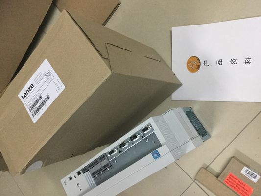
| Place of Origin: | Germany |
| Brand Name: | LENZE |
| Certification: | CE |
| Model Number: | E82EV302K4C200 |
| Minimum Order Quantity: | 1pcs |
|---|---|
| Packaging Details: | carton |
| Delivery Time: | in stock |
| Payment Terms: | T/T, Western Union, MoneyGram |
| Supply Ability: | 100pcs/week |
| LENZE: | LENZE | E82EV302K4C200: | E82EV302K4C200 |
|---|---|---|---|
| Color: | Black | Wire: | Wire |
| Material: | Iron | Temperature: | 20-90 |
| Dimension: | 80mm |
![]()
![]()
![]() Requirements
Requirements
● Read the information in the section Checking before replacing components (Page 257).
| Requirements ● Read the information in the section Checking before replacing components (Page 257). |
Proceed as follows to replace an R/H-CPU in the redundant system: 1. Switch off the supply voltage to the failed R/H-CPU |
| he replacement CPU has the same article number and firmware version as the failed R/H-CPU. |
Remove the connector for the supply voltage. 3. Disconnect the bus connector for the PROFINET ring. Then remove the bus connector from the R/H-CPU. |
| The replacement CPU has a SIMATIC memory card with the correct storage capacity. ● The primary CPU has not disabled SYNCUP (default). Procedure for replacing R/H-CPUs |
For H-CPUs only: Disconnect the redundancy connections (fiber-optic cables) at the HCPU. 5. For H-CPUs only: Pull the synchronization modules out of the H-CPU. |
Remove the failed R/H-CPU.
7. Install the replacement CPU with the SIMATIC memory card inserted and the mode
selector in the STOP position.
8. For H-CPUs only: Insert the synchronization modules in the replacement CPU.
9. For H-CPUs only: Insert the redundancy connections (fiber-optic cables) in the
synchronization modules.
10.Insert the PROFINET cables in the R/H-CPU.
11.Push the connector for the supply voltage into the socket on the R/H-CPU.
12.Switch the supply voltage back on.
13.Switch the replacement CPU to the RUN operating state.This section describes the following replacement scenarios:
R:
● Replace defective PROFINET cable with R.
The PROFINET ring has been interrupted at any given point. You can find additional
information in the section Replacing defective PROFINET cables (Page 265).
● Replace two defective PROFINET cables with R.
The PROFINET ring has been interrupted at two points.
H:
● Replace a defective redundancy connection with H.
A fiber-optic cable has been interrupted.
● Replace defective synchronization module with H.
● Replace two defective redundancy connections with H.
Both fiber-optic cables have been interrupted.
Evaluating the diagnostics buffer
Detailed diagnostics information is provided in the diagnostics buffer of the R/H-CPU. The
entries are particularly useful in the replacement scenarios for the redundancy connections:
● R: They contain information on whether one PROFINET cable or both
PROFINET cables have been interrupted or a port of an R-CPU is defective.
● H: You can access information on whether a fiber-optic cable has been
interrupted or the synchronization module is defective (with additional module
diagnostics).Proceed as follows to replace the defective PROFINET cables:
1. Locate the defective PROFINET cables in the PROFINET ring.
2. Replace the PROFINET cables, one after the other.
3. Restart each of the two CPUs.
Result
The redundant system switches to the RUN-Redundant system state.
Initial situation: Failure of two PROFINET cables simultaneously
Two PROFINET cables in the PROFINET ring have been interrupted at two points
simultaneously (≤ 1500 ms apart).
Both R-CPUs are primary CPUs. The R redundant system is in an undefined system
stateTwo PROFINET cables in the PROFINET ring have been interrupted at two points
simultaneously (≤ 1500 ms apart).
Both R-CPUs are primary CPUs. The R redundant system is in an undefined system
state.
Procedure: Replacing the two PROFINET cables
Proceed as follows to replace the defective PROFINET cables:
1. Immediately switch both R-CPUs to the STOP operating state.
2. Locate the defective PROFINET cables in the PROFINET ring.
3. Replace the PROFINET cables, one after the other.
4. Afterwards, switch the R-CPUs back to the RUN operating state.
Result
The redundant system switches to the RUN-Redundant system stateOne redundancy connection (fiber-optic cable) has been interrupted. Display shows: Single
pairing with information on interface and port.
The H redundant system is in the RUN-Redundant system state.
Procedure: Replacing the redundancy connection
Proceed as follows to replace a defective redundancy connection:
1. Check the X3/X4 LEDs. You can pinpoint the defective redundancy connection on the
basis of which LEDs are off.
2. Check the redundancy connection that you have located with the LEDs.
3. If the redundancy connection is defective, replace the fiber-optic cable.
Result
The defective redundancy connection has been replaced. The X3/X4 LEDs flicker
yellow/green.
11.1.3.3 Replacing defective synchronization module with H
Initial situation
A synchronization module has failed.
The redundant H is in the RUN-Redundant system state.
Procedure: Replacing the synchronization module
Proceed as follows to replace a defective synchronization module: