 |
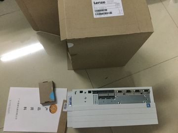
| Place of Origin: | Germany |
| Brand Name: | LENZE |
| Certification: | CE |
| Model Number: | E82EV303k4B |
| Minimum Order Quantity: | 1pcs |
|---|---|
| Packaging Details: | carton |
| Delivery Time: | in stock |
| Payment Terms: | T/T, Western Union, MoneyGram |
| Supply Ability: | 1000pcs/week |
| LENZE: | LENZE | E82EV303k4B: | E82EV303k4B |
|---|---|---|---|
| Material: | Iron | Germany: | Germany |
| Color: | Black | Temperature: | 20-90 |
| Dimension: | 80mm | Wire: | Wire |
![]()
![]()
![]()
![]()
| Check the X3/X4 LEDs on the primary and backup CPU. Locate the defective synchronization module on the basis of which LEDs are off. |
The defective synchronization module has been replaced. The X3/X4 LEDs flicker yellow/green. Maintenance 11.1 Replacing components of the R/H redundant system R/H redundant system |
| . Replace the defective synchronization module. Connect the redundancy connection (fiber-optic cable). |
264 System Manual, 10/2018, A5E41814787-AA 11.1.3.4 Replacing both defective redundancy connections with H Initial situation: Failure of both redundancy connections, one after the other The two redundancy |
| If the X3/X4 LEDs remain off, replace the synchronization module on the other CPU. Result |
connections (fiber-optic cables) have been interrupted one after the other (> 1500 ms apart). The H redundant system is in the RUN-Solo system state. Requirement |
Read the information in the section Checking before replacing components (Page 257).
Procedure: Replacing both redundancy connections
Proceed as follows to replace the defective redundancy connections:
1. Check the X3/X4 LEDs on the primary and backup CPU. If all LEDs are off, both
redundancy connections are defective.
2. Replace the redundancy connections (fiber-optic cables) one after the other.
3. Switch the CPU, which is in STOP mode, to RUN mode.
Result
The defective redundancy connections have been replaced. The redundant system switches
to the RUN-Redundant system state. The X3/X4 LEDs flicker yellow/green.witches to the RUN-Redundant system stateThe PROFINET ring has been interrupted at any given point. The MAINT LEDs on both
CPUs are yellow. The following is shown on the R display: Single pairing with
information on interface and port.
The R/H redundant system is in the RUN-Redundant system state.
Procedure: Replacing the PROFINET cable
Proceed as follows to replace the defective PROFINET cable:
1. Check the X1 P1/X1 P2 LEDs on the primary and backup CPU. LEDs that are off indicate
an interruption to the PROFINET ring.
2. Locate the defective PROFINET cable in the PROFINET ring.
3. Replace the defective PROFINET cable.
Result
The defective PROFINET cable has been replaced.
The X1 P1/X1 P2 LEDs on the primary and backup CPU are yellow. The MAINT LEDs on
both CPUs are off.The SIMATIC memory card of a CPU is defective. System diagnostics reports a system
error. The CPU affected has switched to the STOP operating state.
The R/H redundant system is in the RUN-Solo system state.
Requirement
● Read the information in the section Checking before replacing components (Page 257).
● The new SIMATIC memory card must have sufficient memory for the project.
Procedure
Proceed as follows to replace a defective SIMATIC memory card:
1. Replace the SIMATIC memory card in the CPU in STOP.
2. Switch the CPU to the RUN operating state.
Result
1. The CPU with the replaced SIMATIC memory card runs SYNCUP. SYNCUP transfers the
project data from the primary to the backup CPU.