 |
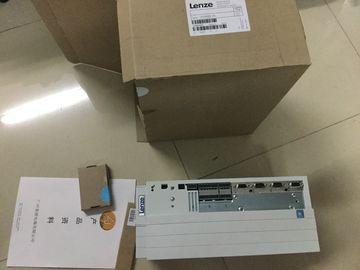
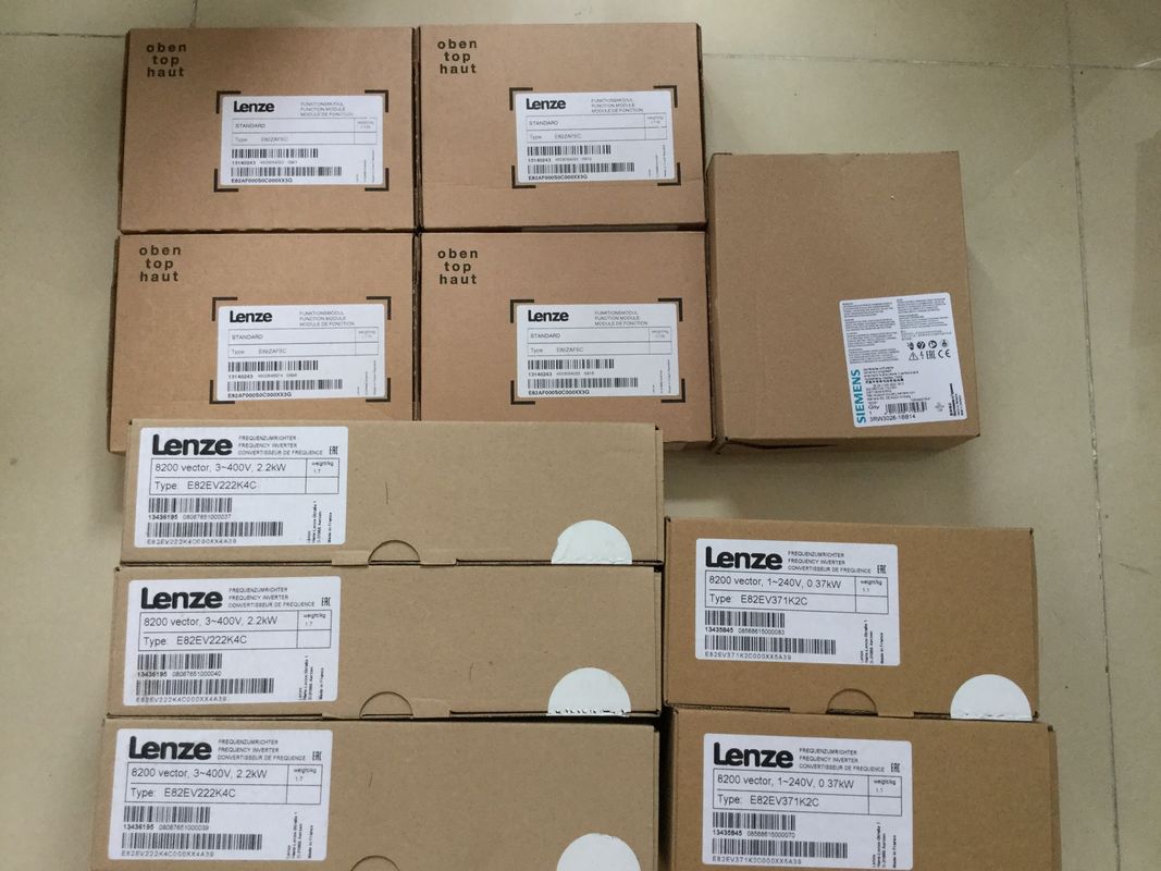
| Place of Origin: | Germany |
| Brand Name: | LENZE |
| Certification: | CE |
| Model Number: | E82EV371K2C |
| Minimum Order Quantity: | 1pcs |
|---|---|
| Packaging Details: | carton |
| Delivery Time: | in stock |
| Payment Terms: | T/T, Western Union, MoneyGram |
| Supply Ability: | 100pcs/week |
| LENZE: | LENZE | E82EV371K2C: | E82EV371K2C |
|---|---|---|---|
| Material: | Iron | Color: | Black |
| Germany: | Germany | Wire: | Wire |
| Temperature: | 20-90 |
![]()
![]()
![]()
![]() The display indicates that the CPU is in STOP and is running a firmware update.
The display indicates that the CPU is in STOP and is running a firmware update.
The display shows a results screen after completion of the firmware update.
| command in the "Project" menu. 4. Use a file selection dialog to navigate to the firmware update file. |
The display indicates that the CPU is in STOP and is running a firmware update. The display shows a results screen after completion of the firmware update. |
| You can then also decide whether to delete the content of the SIMATIC memory card or add the firmware update files to the SIMATIC memory card. |
Remove the SIMATIC memory card after the firmware update is complete. The RUN LED on the CPU lights up in yellow and the MAINT LED flashes yellow. |
| . Insert the SIMATIC memory card with the firmware update files into the CPU. The firmware update begins shortly after the SIMATIC memory card has been inserted. |
If you subsequently wish to use the SIMATIC memory card as a program card, leave the SIMATIC memory card in the CPU |
To do so, after completion of the firmware update,
select the "Convert memory card" menu item on the display.
Alternatively, you can also convert the SIMATIC memory card to a program card in STEP
7.If you perform a firmware update via the SIMATIC memory card, you must use a large
enough card.
Check the specified file sizes of the update files when downloading them from
Industry Online Support. The total size of the update files must not exceed the available
memory size of your SIMATIC memory card.
You can find more information on the capacity of SIMATIC memory cards in the section
Accessories/spare parts (Page 305) and in the function manual Structure and use of the
CPU memoryFor a firmware update of the R/H-CPUs, you must switch both R/H-CPUs to the STOP
operating state. A role change between primary and backup CPU can occur during the
process. The following requirement therefore applies: CPU 1 is the primary CPU. CPU 2 is
the backup CPU.
You must proceed in the following order for retentive data to be retained during a firmware
update:
1. Switch CPU 2 to the STOP operating state.
2. Run the update for CPU 2.
Please note: Ignore any pairing error (incorrect firmware) after CPU 2 startup.
3. Switch CPU 1 to the STOP operating state.
4. Now run the update for CPU 1.
5. Switch CPU 1 to the RUN operating state.
6. Switch CPU 2 to the RUN operating stateThe installation of the firmware update switches the CPUs to the STOP operating state and
therefore the redundant system to the STOP system state. STOP can impact the operation
of an online process or a machine.
Unexpected operation of a process or a machine can lead to fatal or severe injuries and/or
to material damage.
Ensure before installing the firmware update that the CPU is not controlling any active
process.
Installation of the firmware update for R/H-CPU displays
Firmware updates for the R/H-CPU displays should be run in the RUN-Solo system state. A
role change between primary and backup CPU can occur during the process. The following
requirement therefore applies: CPU 1 is the primary CPU. CPU 2 is the backup CPU.
Follow the sequence below:
1. Switch CPU 2 to the STOP operating state.
2. Run the update for the CPU 2 display.
3. Switch CPU 2 to the RUN operating state. Wait until the R/H system switches to the
RUN-Redundant system state.
4. Switch CPU 1 to the STOP operating state.
5. Run the update for the CPU 1 display.
6. Switch CPU 1 to the RUN operating state. Wait until the R/H system switches to the
RUN-Redundant system state.