 |
| Place of Origin: | Germany |
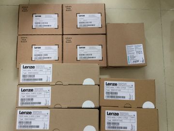
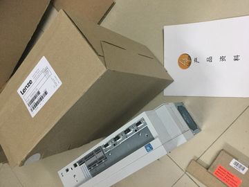
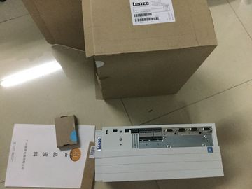
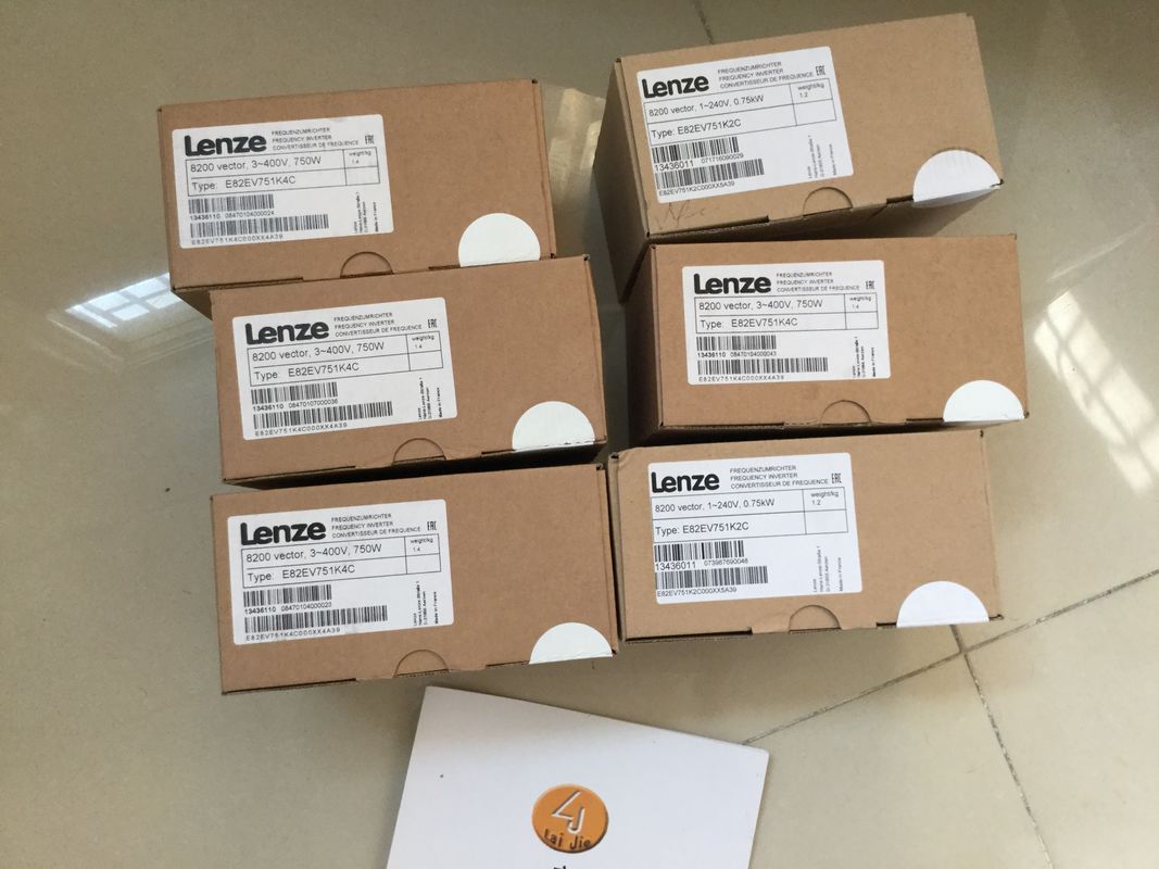
| Brand Name: | LENZE |
| Certification: | CE |
| Model Number: | E82EV402k2B |
| Minimum Order Quantity: | 1pcs |
|---|---|
| Packaging Details: | carton |
| Delivery Time: | in stock |
| Payment Terms: | T/T, Western Union, MoneyGram |
| Supply Ability: | 100pcs/week |
| LENZE: | LENZE | E82EV402k2B: | E82EV402k2B |
|---|---|---|---|
| Germany: | Germany | Temperature: | 20-90 |
| Dimension: | 80mm | Color: | Black |
| Wire: | Wire |
![]()
![]()
![]()
![]()
| Burst pulses (high-speed transient disturbances) | igh-energy single pulse (surge) in accordance with IEC 61000-4-5 External protective circuit required (not for 230 V modules) |
| n accordance with IEC 61000-4-4. |
You can find more information in the Designing interference-free controllers function manual. 3 • Asymmetric coupling ±2 kV (power supply cables) |
| 2 kV (power supply cable) ±2 kV (signal cable > 30 m) |
DC with protective elements ±2 kV (signal/data line only > 30 m), with |
protective elements
• Symmetric coupling ±1 kV (power supply cable) DC with
protective elements
±1 kV (signal/data line only > 30 m), with
protective elementsThe following table shows the electromagnetic compatibility of the R/H redundant
system with respect to sinusoidal disturbances (RF radiation).
Table 13- 2 Sinusoidal disturbances with RF radiation
RF radiation in accordance with IEC 61000-4-3/NAMUR 21
Electromagnetic RF field, amplitude-modulated
Corresponds with degree
of severity
80 to 1000 MHz; 1.4 to 2 GHz 2.0 GHz to 6 GHz
10 V/m 1 V/m 3
80 % AM (1 kHz)
The following table shows the electromagnetic compatibility of the R/H redundant
system with respect to sinusoidal disturbances (RF coupling).
Table 13- 3 Sinusoidal disturbances with RF couplingterference emission of electromagnetic fields in accordance with EN 55016 (measured at a
distance of 10 m).
Table 13- 4 Interference emission of electromagnetic fieldsThe R/H redundant system meets the specifications regarding shippings and
storage conditions pursuant to IEC 61131-2. The following information applies to modules
that are shipped and/or stored in their original packaging.
Shipping and storage conditions for modules
Table 13- 6 Shipping and storage conditionsThe R/H redundant system is designed for stationary use in weather-proof locations.
The operating conditions are based on the requirements of DIN IEC 60721-3-3:
● Class 3M3 (mechanical requirements)
● Class 3K3 (climatic requirements)
Test of mechanical ambient conditions
The table below provides important information with respect to the type and scope of the test
of ambient mechanical conditions.
Table 13- 7 Test of mechanical ambient conditionsVibration Vibration test according
to IEC 60068-2-6
(Sinus)
Type of oscillation: Frequency sweeps with a rate of change of 1 octave/minute.
5 Hz ≤ f ≤ 8.4 Hz, constant amplitude 7 mm
8.4 Hz ≤ f ≤ 150 Hz, constant acceleration 2 g
Duration of oscillation: 10 frequency sweeps per axis, along each of the 3
mutually perpendicular axes
Shock Shock, tested according
to IEC 60068-2-27
Type of shock: Half-sine
Shock intensity: 15 g max., duration 11 ms
Direction of shock: 3 shocks each in (+/-) direction, along each of the 3
mutually perpendicular axes
Continuous shock Shock, tested according
to IEC 60068-2-27
Type of shock: Half-sine
Shock intensity: 250 m/s2 peak value, 6 ms duration
Direction of shock: 1000 shocks each in (+/-) direction, along each of the
3 mutually perpendicular axes
Reduction of vibrations