|
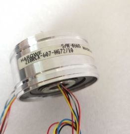
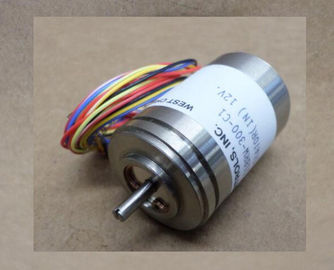
| Place of Origin: | GERMANY |
| Brand Name: | HAROWE |
| Certification: | CE |
| Model Number: | 21BRCX-500-H49A |
| Minimum Order Quantity: | 1pcs |
|---|---|
| Packaging Details: | carton |
| Delivery Time: | in stock |
| Payment Terms: | T/T, Western Union, MoneyGram |
| Supply Ability: | 100pcs/week |
| HAROWE: | HAROWE | 21BRCX-500-H49A: | 21BRCX-500-H49A |
|---|---|---|---|
| GERMANY: | GERMANY | Material: | Iron |
| Color: | Black | Temperature: | 20-90 |
| Wire: | Wire | Dimension: | 90mm |
| the TIA Portal. General function overview: |
|
| Network browsing and creation of a table showing the accessible devices in the network. | |
| Flashing of device LEDs or HMI display to locate a device |
Downloading of addresses (IP, subnet, gateway) to a device
● Downloading the PROFINET name (station name) to a device
● Placing a CPU in RUN or STOP mode
● Setting the time in a CPU to the current time of your PG/PC
● Downloading a new program to a CPU or an HMI device
● Downloading from CPU, downloading to CPU or deleting recipe data from a CPU
● Downloading from CPU or deleting data log data from a CPU
● Backup/restore of data from/to a backup file for CPUs and HMI devices
● Downloading service data from a CPU
● Reading the diagnostics buffer of a CPU
● Performing a CPU memory reset
● Resetting devices to factory settings
● Downloading a firmware update to a device
You can find the SIMATIC Automation Tool on the With PRONETA (PROFINET network analysis), you analyze the PROFINET
network during commissioning. PRONETA features two core functions:
● The topology overview independently scans PROFINET network and all connected
components.
● The IO check is a fast test of the wiring and the module configuration of a system.
You can find PRONETA on the SINETPLAN, the Network Planner, supports you in planning automation systems
and networks based on PROFINET. The tool facilitates professional and predictive
dimensioning of your PROFINET installation as early as in the planning stage. In addition,
SINETPLAN supports you during network optimization and helps you to exploit network
resources optimally and to plan reserves. This helps to prevent problems in commissioning
or failures during productive operation even in advance of a planned operation. This
increases the availability of the production plant and helps improve operational safety.
The advantages at a glance
● Network optimization thanks to port-specific calculation of the network load
● Increased production availability thanks to online scan and verification of existing systems
● Transparency before commissioning through importing and simulation of existing STEP 7
projects
● Efficiency through securing existing investments in the long term and optimal exploitation
of resources
You can find SINETPLAN on the The module has the following technical properties:
● 4 analog outputs
● Selection of channels for voltage output
● Selection of channels for current output
● Resolution: 16 bits including sign
Configurable diagnostics (per channel)rmware update V1.0.0 or higher V12 or higher --- / X
Identification data I&M0 to I&M3 V1.0.0 or higher V12 or higher X
Parameter assignment in RUN V1.0.0 or higher V12 or higher X
Calibration in runtime V1.0.0 or higher V12 or higher X
Module-internal Shared Output (MSO) V2.0.0 or higher V13 Update 3 or
higher
(PROFINET IO
only)
X
(PROFINET IO only)
Configurable submodules / submodules for
Shared Device
V2.0.0 or higher V13 Update 3 or
higher
(PROFINET IO
only)
X
(PROFINET IO only)
Configurable after interface module
IM 155-5 DP ST
V2.0.0 or higher V13 or higher X
You can configure the module with STEP 7 (TIA Portal) and with a GSD file.
Compatibility
The following table shows the compatibility of the modules and the dependencies between
hardware functional status (FS) and firmware version (FW) used:
Hardware functional status Firmware version Note
FS01 V1.0.0 to V2.0.x Upgrade to downgrade possible between
V1.0.0 and V2.0.x FS02 V1.0.0 to V2.0.x
FS03 V2.1.0 No upgrade or downgrade possible
FS04 V2.2.0 or higher Upgrade and downgrade possible between
V2.2.0 and higher
Accessories
The following accessories are supplied with the module and can also be ordered separately
as spare parts:
● Shield bracket
● Shield terminal
● Power supply element
● Labeling strips
● U connector
● Universal front doorhe following component can be ordered separately:
Front connectors, including potential jumpers and cable ties
You can find additional information on accessories in the system manual /ET 200MPThis section contains the block diagram of the module and outlines various connection
options.
You can find information on wiring the front connector, creating a cable shield, etc. in the
Wiring section of the system manual /ET 200MP QVn Voltage output channel
QIn Current output channel
Sn+/Sn- Sense line channel
L+ Connection for supply voltage
M Ground connection
MANA Reference potential of the analog circThe power supply element is plugged onto the front connector for powering the analog
module. Wire the supply voltage to terminals 41 (L+) and 44 (M). Use terminals 42 (L+) and
43 (M) to loop the potential to the next module.The following figure shows an example of the wiring options:
● 2-wire connection, without compensation for line resistances.
● 4-wire connection, with compensation for line resistancesThe following figure shows an example of the pin assignment for current output circuitry① Load on current outputs CHx Channel or 4 x channel status (green/red)