 |
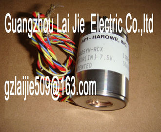
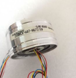
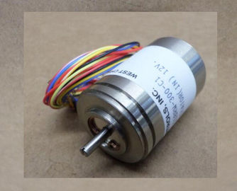
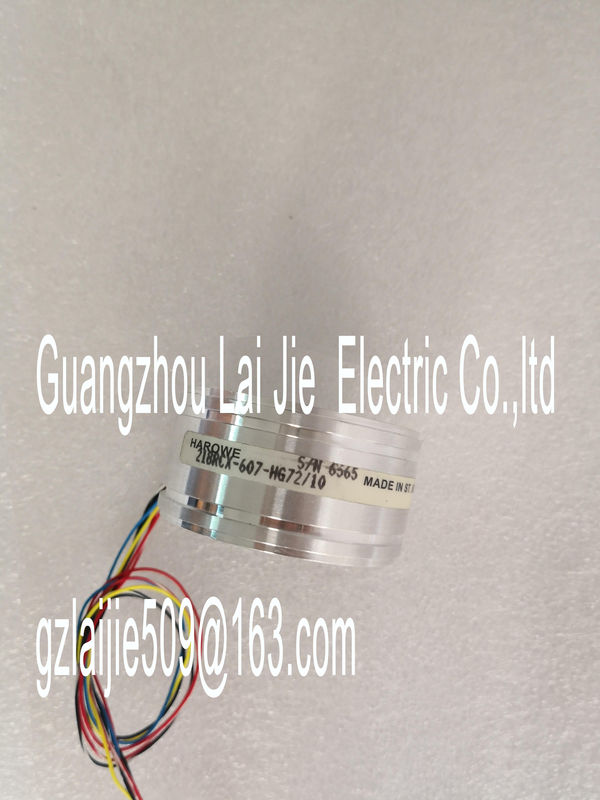
| Place of Origin: | GERMANY |
| Brand Name: | HAROWE |
| Certification: | CE |
| Model Number: | 21BRCX-500-H7 |
| Minimum Order Quantity: | 1pcs |
|---|---|
| Packaging Details: | carton |
| Delivery Time: | in stock |
| Payment Terms: | T/T, Western Union, MoneyGram |
| Supply Ability: | 100pcs/week |
| HAROWE: | HAROWE | 21BRCX-500-H7: | 21BRCX-500-H7 |
|---|---|---|---|
| GERMANY: | GERMANY | Material: | Iron |
| Color: | Black | Temperature: | 20-90 |
| Dimension: | 90mm |
| Digital-to-analog converter (DAC) RUN Status display LED (green) | |
| Backplane bus interface ERROR Error display LED (red) | |
| upply voltage via power supply module PWR LED for power supply (green) Figure 3-3 Block diagram and pin assignment for the curreThe module is set to voltage output type |
by default with output range ±10 V. You need to edit
the module parameters with STEP 7 if you want to use a different output range or output
type.
Output type and output ranges
The following table shows the output type and the respective output ranges.
Table 4- 1 Output type and output rangeshen you assign the module parameters in STEP 7, you use various parameters to specify
the module properties. The following table lists the configurable parameters. The effective
range of the configurable parameters depends on the type of configuration. The following
configurations are possible:
● Central operation with a CPU
● Distributed operation on PROFINET IO in an ET 200MP system
● Distributed operation on PROFIBUS DP in an ET 200MP system
When assigning parameters in the user program, use the WRREC instruction to transfer the
parameters to the module by means of data records; see chapter Parameter assignment and
structure of the parameter data record. (Page 35) If you enable diagnostics for multiple channels, you will receive an alarm surge on failure of the supply voltage because
each enabled channel will detect this fault. You can prevent this message burst by assigning the diagnostics function to
one channel only.
** You can set the effective range of the diagnostics for each channel in the user program with data records 64 to 67.
Short-circuit detection
The diagnostics for short circuit to ground can be configured for the voltage output type. A
short-circuit detection is not possible for small output values; the output voltages must
therefore be below -0.1 V or above +0.1 V.
Open-circuit detection
The diagnostics for open circuit can be configured for the current output type. An open-circuit
detection is not possible for small output values; the output voltages must therefore be below
-0.2 mA or above +0.2 mA.Enabling of the diagnostics, with missing or too little supply voltage L+.
Wire break
Enabling of the diagnostics if the line to the actuator is broken.
Short-circuit to ground
Enabling of the diagnostics if a short-circuit of the output to MANA occurs.
Overflow
Enabling of the diagnostics when the output value exceeds the overrange.
Underflow
Enabling of the diagnostics when the output value violates the underrange.
Reaction to CPU STOP
Determines the reaction of the output to the CPU going into STOP state.
Substitute value
The substitute value is the value that the module outputs in case of a CPU STOPThe module can be configured differently in STEP 7; see following table. Depending on the
configuration, additional/different addresses are assigned in the process image of the
outputs/inputs.
Configuration options of AQ 4xU/I ST
You can configure the module with STEP 7 (TIA Portal) or with a GSD file.
When you configure the module by means of the GSD file, the configurations are available
under different abbreviations/module names.
The following configurations are possible:The value status is always activated for the following module names:
● AQ 4xU/I ST QI
● AQ 4xU/I ST S QI
● AQ 4xU/I ST MSO
An additional bit is assigned to each channel for the value status. The bit for the value status
indicates if the output value specified by the user program is actually pending at the module
terminal (0 = value is incorrect)The following figure shows the address space allocation for the configuration as 4-channel
module. You can freely assign the start address for the module. The addresses of the
channels are derived from the start address.
"QB x" stands, for example, for the module start address output byte xFor the configuration as a 4 x 1-channel module, the channels of the module are divided into
multiple submodules. The submodules can be assigned to different IO controllers when the
module is used in a shared device.
The number of usable IO controllers depends on the interface module used. Observe the
information in the manual for the particular interface module.
Unlike the 1 x 4-channel module configuration, each of the four submodules has a freely
assignable start addresschannels 0 to 3 of the module are copied to multiple submodules. Channels 0 to 3 are then
available with identical values in various submodules. These submodules can be assigned to
up to four IO controllers when the module is used in a shared device.
● The IO controller to which submodule 1 is assigned has write access to outputs 0 to 3.
● The IO controllers to which submodule 2, 3, or 4 is assigned have read access to outputs
0 to 3.
The number of usable IO controllers depends on the interface module use