|
| Place of Origin: | GERMANY |
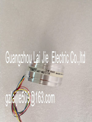
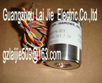
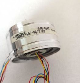
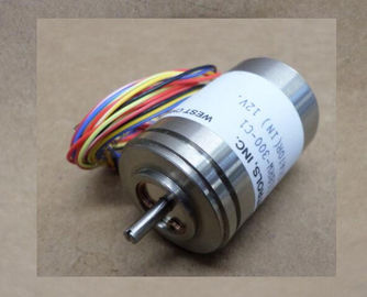
| Brand Name: | HAROWE |
| Certification: | CE |
| Model Number: | 21BRCX-500-H7-01 |
| Minimum Order Quantity: | 1pcs |
|---|---|
| Packaging Details: | carton |
| Delivery Time: | in stock |
| Payment Terms: | T/T, Western Union, MoneyGram |
| Supply Ability: | 100pcs/week |
| HAROWE: | HAROWE | 21BRCX-500-H7-01: | 21BRCX-500-H7-01 |
|---|---|---|---|
| GERMANY: | GERMANY | Material: | Iron |
| Color: | Black | Temperature: | 20-90 |
| Wire: | Wire |
| PROFIBUS as of GSD version/GSD revision V1.0 / V5.1 |
|
| PROFINET as of GSD version/GSD revisionReparameterization possible in RUN Yes Calibration possible in RUN Yes |
|
| Supply voltage Rated value (DC) 24 V |
permissible range, lower limit (DC) 20.4 V
permissible range, upper limit (DC) 28.8 V
Reverse polarity protection Yes
Input current
Current consumption, max. 190 mA; with 24 V DC supplyAnalog outputs
Number of analog outputs 4
Voltage output, short-circuit protection Yes
Voltage output, short-circuit current, max. 24 mA
Current output, no-load voltage, max. 22 V
Cycle time (all channels), min. 3.2 ms; independent of number of activated
channels
• for voltage output two-wire connection Yes
• for voltage output four-wire connection Yes
• for current output two-wire connection Yes
Load impedance (in rated range of output)
• with voltage outputs, min. 1 kΩ; 0.5 kOhm at 1 to 5 V
• with voltage outputs, capacitive load, max. 1 µF
• with current outputs, max. 750 Ω
• with current outputs, inductive load, max. 10 mH
Cable length
• shielded, max. 800 m; for current, 200 m for voltage
Analog value generation for the outputs
Integration and conversion time/resolution per
channel
• Resolution with overrange (bit including
sign), max.
16 bit
• Conversion time (per channel) 0.5 msIsochronous operation (application synchronized
up to terminal)
No
Interrupts/diagnostics/status information
Diagnostics function Yes
Substitute values connectable Yes
Alarms
• Diagnostic alarm Yes
Diagnostic messages
• Monitoring the supply voltage Yes
• Wire-break Yes; Only for output type "current"
• Short-circuit Yes; Only for output type "voltage"
• Overflow/underflow Yes
Diagnostics indication LED
• RUN LED Yes; Green LED
• ERROR LED Yes; Red LED
• Monitoring of the supply voltage (PWRLED)
Yes; Green LED
• Channel status display Yes; Green LED
• for channel diagnosticsfor module diagnostics Yes; Red LED
Potential separation
Potential separation channels
• between the channels No
• between the channels, in groups of 4
• between the channels and backplane bus Yes
• Between the channels and load voltage L+ Yes
Permissible potential difference
between S- and MANA (UCM) 8 V DC
Isolation
Isolation tested with 707 V DC (type test)
Decentralized operation
Prioritized startup No
Dimensions
Width 35 mm
Height 147 mm
Depth 129 mm
Weights
Weight, approx. The dimensional drawing of the module on the mounting rail, as well as a dimensional
drawing with open front panel are provided in the appendix. Always observe the specified
dimensions for installation in cabinets, control rooms, etc. The data records of the module have an identical structure, regardless of whether you
configure the module with PROFIBUS DP or PROFINET IO.
Dependencies for configuration with GSD file
When configuring the module with a GSD file, remember that the settings of some
parameters are dependent on each other. The parameters are only checked for plausibility
by the module after the transfer to the module.
The following table lists the parameters that depend on one another.You have the option to assign module parameters in RUN (e.g., the voltage or current values
of selected channels can be edited in RUN without having an effect on the other channels).
Parameter assignment in RUN
The WRREC instruction is used to transfer the parameters to the module using data records
64 to 67. The parameters set in STEP 7 do not change in the CPU, which means the
parameters set in STEP 7 are still valid after a restart.
The parameters are only checked for plausibility by the module after the transfer to the
module.
Output parameter STATUS
The module ignores errors that occurred during the transfer of parameters with the WRREC
instruction and continues operation with the previous parameter assignment. However, a
corresponding error code is written to the STATUS output parameter.
The description of the WRREC instruction and the error codes is available in the STEP 7
online helpf the module is operated behind a PROFIBUS DP interface module, the parameter data
records 0 and 1 are not read back. You get the diagnostics data records 0 and 1 for the read
back parameter data records 0 and 1. You can find more information in the Interrupts section
of the PROFIBUS DP interface module device manual on the The channel parameters in data records 64 to 67 are available for 1x 4-channel configuration
and are assigned as follows:
● Data record 64 for channel 0
● Data record 65 for channel 1