|
| Place of Origin: | GERMANY |
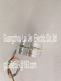
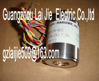
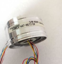
| Brand Name: | HAROWE |
| Certification: | CE |
| Model Number: | 21BRCX-500-H74 |
| Minimum Order Quantity: | 1pcs |
|---|---|
| Packaging Details: | carton |
| Delivery Time: | in stock |
| Payment Terms: | T/T, Western Union, MoneyGram |
| Supply Ability: | 100pcs/week |
| HAROWE: | HAROWE | 21BRCX-500-H74: | 21BRCX-500-H74 |
|---|---|---|---|
| GERMANY: | GERMANY | Material: | Iron |
| Color: | Black | Temperature: | 20-90 |
| Dimension: | 90mm | Wire: | Wire |
| Data record 66 for channel 2 ● Data record 67 for channel 3 |
|
| For configuration 4 x 1-channel, the module has 4 submodules with one channel each. The parameters for the channel are available in data record 64 and are assigned as follows: |
|
| Data record 64 for channel 0 (submodule 1) ● Data record 64 for channel 1 (submodule 2) |
Data record 64 for channel 2 (submodule 3)
● Data record 64 for channel 3 (submodule 4)
Address the respective submodule for data record transfer.The example in the following figure shows the structure of data record 64 for channel 0. The
structure of channels 1 to 3 is identical. The values in byte 0 and byte 1 are fixed and may
not be changed.
Enable a parameter by setting the corresponding bit to "1The following table lists all output types of the analog output module along with their codes.
Enter these codes at byte 2 of the data record for the corresponding channel (see the
previous figure).The following table lists all voltage and current output ranges of the analog output module
along with their codes. In each case, enter these codes at byte 3 of the respective data
record (see previous figure).
Table B- 3 Output range code
The following table lists all output ranges for the valid substitute values. Enter these
substitute values at bytes 6 and 7 of the data record for the corresponding channel (see the
previous figure). The binary representation of output ranges is available on the in
Function Manual Analog value processing for SIMATIC.The following table lists all output ranges for the valid substitute values. Enter these
substitute values at bytes 6 and 7 of the data record for the corresponding channel (see the
previous figure). The binary representation of output ranges is available on the in
Function Manual Analog value processing for SIMATIC.is appendix describes the analog values for all output ranges supported by the AQ 4xU/I
ST analog module.
Measured value resolution
Each analog value is written left aligned to the tags. The bits marked with "x" are set to "0".
Table C- 1 Resolution of the analog valuesThe tables below set out the digitalized representation of the output ranges by bipolar and
unipolar range. The resolution is 16 bits.Representation of analog values in the voltage output ranges
The tables below list the decimal and hexadecimal values (codes) of the possible voltage
output ranges.
Table C- 4 Voltage output range ±10 VThis manual contains notices you have to observe in order to ensure your personal safety, as well as to prevent
damage to property. The notices referring to your personal safety are highlighted in the manual by a safety alert
symbol, notices referring only to property damage have no safety alert symbol. These notices shown below are
graded according to the degree of dangendicates that minor personal injury can result if proper precautions are not taken.
NOTICE
indicates that property damage can result if proper precautions are not taken.
If more than one degree of danger is present, the warning notice representing the highest degree of danger will
be used. A notice warning of injury to persons with a safety alert symbol may also include a warning relating to