|
| Place of Origin: | GERMANY |
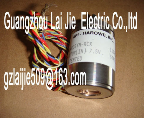
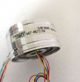
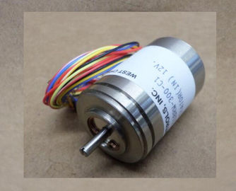
| Brand Name: | HAROWE |
| Certification: | CE |
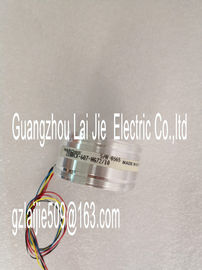
| Model Number: | 21BRCX-500-H7/15 |
| Minimum Order Quantity: | 1pcs |
|---|---|
| Packaging Details: | carton |
| Delivery Time: | in stock |
| Payment Terms: | T/T, MoneyGram, Western Union |
| Supply Ability: | 100pcs/week |
| HAROWE: | HAROWE | Material: | Iron |
|---|---|---|---|
| Color: | Black | Temperature: | 20-90 |
| Wire: | Wire | Dimension: | 90mm |
| Germany: | Germany |
| the information in the manual for the particular interface moduleThe meaning of the value status depends on the submodule on which it occurs. | |
| For the 1st submodule (=basic submodule), the value status 0 indicates that the value is incorrect or that the IO controller of the basic submodule is in STOP state |
|
| For the 2nd to 4th submodule (=MSO submodule), the value status 0 indicates that the value is incorrect or one of the following errors has occurred: |
The basic submodule is not yet configured (not ready).
● The connection between the IO controller and the basic submodule has been interrupted.
● The IO controller of the basic submodule is in STOP or POWER OFF state.
The figure below shows the assignment of the address space with submodules 1 and 2.You can find information on the Shared Input/Output (MSI/MSO) function in the section
Module-Internal Shared Input/Output (MSI/MSO) of the PROFINET with STEP 7 Vhe following tables explain the meaning of the status and error displays. Remedial
measures for diagnostic reports can be found in chapter Diagnostics alarms (Page 28).
RUN and ERROR LED
Table 5- 1 Status and error displays RUN and ERROR
LED Meaning Solution
RUN ERROR
Off Off
Voltage missing or too low at backplane bus • Switch on the CPU and/or the system power
supply modules.
• Verify that the U connectors are inserted.
• Check whether too many modules are inserted.
Flashes Off
The module starts and flashes until the valid
parameter assignment is set.
---
On Off
Module is configured
On Flashes
Indicates module errors (at least one error at
one channel, e.g., wire break).
Evaluate the diagnostics data and eliminate the
error (e.g., wire break).
Flashes Flashes
Hardware defective Replace the module.The analog output module AQ 4xU/I ST supports diagnostic interrupts.
You can find detailed information on the event in the error organization block with the
"RALRM" instruction (read additional interrupt info) and in the STEP 7 online help.
Diagnostic interrupt
The module generates a diagnostic interrupt at the following events:
● Missing supply voltage L+
● Short-circuit to ground
● Wire break
● Overflow
● Underflow
● Parameter assignment errorA diagnostics alarm is generated and the ERROR LED flashes on the module for each
diagnostics event. The diagnostics alarms can be read out in the diagnostics buffer of the
CPU, for example. You can evaluate the error codes with the user program.
If the module is operated distributed with PROFIBUS DP in an ET 200MP system, you have
the option to read out diagnostics data with the instruction RDREC or RD_REC using data
record 0 and 1. The structure of the data records is available on the in the "Manual
for interface module IM 155-5 DP ST (6ES7155-5BA00-0AB0)".Overload at output Eliminate overload
Short-circuit of output QV to MANA Eliminate the short-circuit
Wire break 6H Actuator circuit impedance too high Use a different actuator type or modify the
wiring, for example, use cables with larger
cross-section
Wirebreak between the module and
actuator
Connect the cable
Channel not connected (open) • Disable the channel ("output type"
parameter)
• Connect the channel
Overflow 7H The output value set by the user program
violates the valid rated
range/overrange.
Correct the output value
Underflow 8H The output value set by the user program
violates the valid rated
range/underrange.
Correct the output value
Parameter assignment
error
10H • The module cannot evaluate parameters
for the channel
• Incorrect parameter assignment
Correct the parameter assignment
Load voltage missing 11H Supply voltage L+ of the module is missing
Connect supply voltage L+ to moduleThe following table shows the technical specifications as of 08/2018. You will find a data
sheet including daily updated technical specifications on the HW functional status FS04
Firmware version V2.2.0
• FW update possible Yes
Product function
• I&M data Yes; I&M0 to I&M3
• Output range scalable No
Engineering with
• STEP 7 TIA Portal configurable/integrated
as of version
V12 / V12
• STEP 7 configurable/integrated as of version
V5.5 SP3 / -