|
| Place of Origin: | GERMANY |
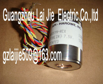
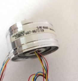
| Brand Name: | HAROWE |
| Certification: | CE |
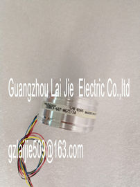
| Model Number: | 15BRCX-500-F36HV/10 |
| Minimum Order Quantity: | 1pcs |
|---|---|
| Packaging Details: | carton |
| Delivery Time: | in stock |
| Payment Terms: | T/T, Western Union, MoneyGram |
| Supply Ability: | 100pcs/week |
| HAROWE: | HAROWE | 15BRCX-500-F36HV/10: | 15BRCX-500-F36HV/10 |
|---|---|---|---|
| Material: | Iron | Color: | Black |
| Temperature: | 20-90 | Dimension: | 90mm |
| Wire: | Wire | Germany: | Germany |
| Current per group, max. 2 A; see additional description in the manual | |
| Current per module, max. 32 A; see additional description in the manual | |
| Relay outputs Number of relay outputs 16 |
Rated input voltage of relay coil L+ (DC) 24 V
Current consumption of relays (coil current of all
relays), max.
150 mA
External fuse for relay outputs Circuit breaker B10 / B16
Contact connection (internal) No
Size of motor starter according to NEMA, max. 5
Number of switching cycles, max. See additional description in the manual
Relay approved acc. to UL 508 No
Switching capacity of the contacts
? With inductive load, max. 2 A; see additional description in the manual
? With resistive load, max. 2 A; see additional description in the manual
Cable length
Shielded, max. 1000 m
Unshielded, max. 600 m
Isochronous mode
Isochronous mode (application synchronized up to
terminal)
No
Interrupts/diagnostics/status information
Substitute values can be applied Yes
Interrupts
Diagnostics interruptDiagnostics Yes
Monitoring of supply voltage Yes
Wire break No
Short-circuit No
Diagnostics indicator LED
RUN LED Yes; green LED
ERROR LED Yes; red LED
Monitoring of supply voltage (PWR LED) Yes; green LED
Channel status display Yes; green LED
For channel diagnostics No
For module diagnostics Yes; red LED
Electrical isolation
Electrical isolation of channels
Between the channels No
Between the channels, in groups of 2
Between the channels and the backplane bus Yes
Between the channels and the load voltage L+ Yes
Permitted potential difference
Between different circuits 75 V DC/60 V AC (basic insulation) between the
backplane bus and the supply voltage L+; 250 V
AC between the channels and the supply voltage
L+; 250 V AC between the channels and the
backplane bus; 500 V AC between the channels
Insulation
Insulation tested with Between the channels: 2500 V DC; between the
channels and backplane bus: 2500 V DC; between
L+ and backplane bus 707 V DC (type
test)
Distributed operation
Prioritized startup Yes
Dimensions
Width 35 mm
Height 147 mm
Depth 129 mm
Weights
Weight, approx. 350 gThe following tables list the permissible number of switching cycles depending on the applied
voltage and current load. Different values apply in each case to resistive and inductive loads.
Table 6- 1 Switching capacity and service life of relay contacts for resistive load
The following graphs show the loading capacity of the relay contacts in relation to the
mounting position and the ambient temperature. The total current of the outputs remains
unaffected.The dimension drawing of the module on the mounting rail, as well as a dimension drawing
with open front cover, are provided in the appendix. Always observe the specified
dimensions for installation in cabinets, control rooms, etcThe data records of the module have an identical structure, regardless of whether you
configure the module with PROFIBUS DP or PROFINET IO.
Dependencies for configuration with GSD file
When a GSD file is used to configure a module, dependencies can arise when "assigning the
parameters".
There are no dependencies for this module. You can assign the individual parameters in any
combination.