 |
| Place of Origin: | GERMANY |
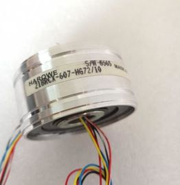
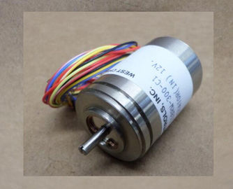
| Brand Name: | HAROWE |
| Certification: | CE |
| Model Number: | 21BRCX-500-F15 |
| Minimum Order Quantity: | 1pcs |
|---|---|
| Packaging Details: | carton |
| Delivery Time: | in stock |
| Payment Terms: | T/T, MoneyGram, Western Union |
| Supply Ability: | 100pcs/week |
| HAROWE: | HAROWE | Material: | Iron |
|---|---|---|---|
| Temperature: | 20-90 | Dimension: | 90mm |
| Germany: | Germany | 21BRCX-500-F15: | 21BRCX-500-F15 |
| Wire: | Wire |
| compensation of line resistance | |
| for resistance measurement with four-wire connection Yes; all measuring ranges except PTCLinearity error (in relation to input range), (+/-) 0,02 % |
|
| Temperature error (in relation to input range), (+/-) 0.005%/K; for TC typ. T 0.02 +/- %/K Crosstalk between the inputs, max. -80 dB |
Repeat accuracy in settled state at 25 °C (in relation
to input range), (+/-)
0.02 %
Temperature errors of internal compensation +/-6 °C
Operational limits across the entire temperature
range
Voltage in relation to input range, (+/-) 0.3 %
Current in relation to input range, (+/-) 0.3 %
Resistance in relation to input range, (+/-) 0.3 %
Resistance thermometer in relation to input range,
(+/-)
0.3 %;
Pt xxx Standard: ±1.5 K,
Pt xxx Climate: ±0.5 K,
Ni xxx Standard: ±0.5 K,
Ni xxx Climate: ±0.3 K
Thermocouple in relation to input range, (+/-) 0.3 %;
Type B: >600°C +/- 4.6K
Type E: >-200°C +/- 1.5K
Type J: >-210°C +/- 1.9K
Type K: >-200°C +/- 2.4K
Type N: >-200°C +/- 2.9K
Type R: >0°C +/- 4.7K
Type S: >0°C +/- 4.6K
Type T: >-200°C +/- 2.4 K
Basic error limit (operational limit at 25 °C)
Voltage in relation to input range, (+/-) 0,1 %
Current in relation to input range, (+/-) 0,1 %
Resistance in relation to input range, (+/-) 0,1 %
Resistance thermometer in relation to input range,
(+/-)
0.1 %;
Pt xxx Standard: ±0.7 K,
Pt xxx Climate: ±0.2 K,
Ni xxx Standard: ±0.3 K,
Ni xxx Climate: ±0.15 K
Thermocouple in relation to input range, (+/-) 0.1 %;
Type B: >600°C +/- 1.7K
Type E: >-200°C +/- 0.7K
Type J: >-210°C +/- 0.8K
Type K: >-200°C +/- 1.2K
Type N: >-200°C +/- 1.2K
Type R: >0°C +/- 1.9K
Type S: >0°C +/- 1.9K
Type T: >-200°C +/- 0.8KSeries mode interference (peak value of interference
< rated value of input range), min.
40 dB
Common mode voltage, max. 10 V
Common mode interference, min. 60 dB
Interrupts/diagnostics/status information
Interrupts
Diagnostics interrupt Yes
Limit interrupt Yes; two high limits and two low limits each
Diagnostics alarms
Diagnostics Yes
Monitoring of supply voltage Yes
Wire break Yes, only for 1 ... 5V, 4 ... 20mA, TC, R and RTD
Overflow/underflow Yes
Diagnostics display LED
RUN LED Yes; green LED
ERROR LED Yes; red LED
Monitoring of supply voltage Yes; green LED
Channel status display Yes; green LED
For channel diagnostics Yes; red LED
For module diagnostics Yes; red LED
Electrical isolation
Electrical isolation channels
Between the channels No
Between the channels, in groups of 4
Between the channels and the backplane bus Yes
Between the channels and the supply voltage of
the electronics
Yes
Permissible potential difference
Between the inputs (UCM) 20 V DC
Between inputs and MANA (UCM) 10 V DC
Between M internally and the inputs 75 V DC / 60 V AC (basic isolation)
Isolation
Isolation tested with 707 V DC (type test)
Distributed mode
Prioritized startup No
Dimensions
Width 25 mm
Height 147 mm
Depth 129 mmPackage includes 40-pin push-in front connector
Additional basic error and noise for integration
time = 2.5 ms: Voltage: +/- 250 mV:
+/- 0.02% +/- 80mV: +/- 0.05% +/- 50 mV: +/-
0.05% resistance: 150 ohm: +/- 0.02% resistance
thermometer: Pt100 climate: +/- 0.08 K
Ni100 Climate: +/-0.08K thermocouple: Type B,
R, S:
+/- 3K Type E, J, K, N, T: +/-1 KThe dimension drawing of the module on the mounting rail, as well as a dimension drawing
with open front panel are provided in the appendix. Always adhere to the specified
dimensions for installation in cabinets, control rooms, etc.
The data records of the module have an identical structure, regardless of whether you
configure the module with PROFIBUS DP or PROFINET IO.
Dependencies for configuration with GSD file
When configuring the module with a GSD file, remember that the settings of some
parameters are dependent on each other. The parameters are only checked for plausibility
by the module after the transfer to the module.
The following table lists the parameters that depend on one another.
Table B- 1 Dependencies of parameters for configuration with GSD file