|
| Place of Origin: | GERMANY |
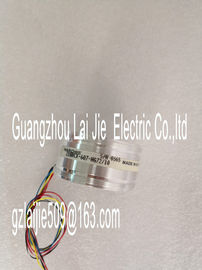
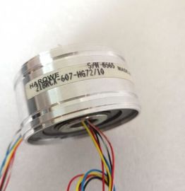
| Brand Name: | HAROWE |
| Certification: | CE |
| Model Number: | 11BRW-300-C-58 |
| Minimum Order Quantity: | 1pcs |
|---|---|
| Packaging Details: | carton |
| Delivery Time: | in stock |
| Payment Terms: | Western Union, MoneyGram, T/T |
| Supply Ability: | 100pcs/week |
| HAROWE: | HAROWE | 11BRW-300-C-58: | 11BRW-300-C-58 |
|---|---|---|---|
| GERMANY: | GERMANY | Color: | Black |
| Temperature: | 20-90 | Dimension: | 90mm |
| Material: | Iron |
| submodules with configuration 1 x 16-channel module (Module-internal shared input, MSI). Channels 0 to 15 are then |
|
| available with identical input values in different submodules. These submodules can be assigned to up to four IO controllers when the module is used in a shared device. Each |
|
| IO controller has read access to the same channels. The number of usable IO controllers depends on the interface module used. Please observe |
the information in the manual for the particular interface module.The meaning of the value status depends on the submodule involved.
For the 1st submodule (=basic submodule), the value status is not relevant.
For the 2nd to 4th submodule (=MSI submodule), the value status 0 indicates that the basic
submodule parameters have not yet been assigned (not ready).
The figure below shows the assignment of the address space with submodules 1 and 2.You can find information on the module-internal shared input/shared output (MSI/MSO)
function in the section Module-internal shared input/shared output (MSI/MSO) of the function
manual PROFINET with STEP 7 V13The figure below shows the LED displays (status and error displays) of the
DI 16x230VAC BA.The following table explains the meaning of the status and error displays.
RUN and ERROR LED
Table 5- 1 Status and error displays RUN and ERROR
LED Meaning Remedy
RUN ERROR
Off Off
Voltage missing or too low at backplane bus • Switch on the CPU and/or the system power
supply modules.
• Verify that the U connectors are inserted.
• Check to see if too many modules are inserted.
Flashes Off
Module starts up ---
On Off
Module is ready
Flashes Flashes
Hardware defective Replace the moduleProduct type designation DI 16x230VAC BA
Hardware functional status FS01
Firmware version V2.0.0
• FW update possible Yes
Product function
I&M data Yes; I&M0 to I&M3
Engineering with
STEP 7 TIA Portal can be configured/integrated
as of version
V12 / V12
STEP 7 can be configured/integrated as of version V5.5 SP3 / -
PROFIBUS as of GSD version/GSD revision V1.0 / V5.1
PROFINET as of GSD version/GSD revision V2.3 / -
Operating mode
DI Yes
Counters No
MSI Yes
Power
Power consumption from the backplane bus 1 W
Power loss
Power loss, typ. 4.9 W
Digital inputs
Number of inputs 16
Configurable digital inputs No
Sinking/sourcing input Sinking input
Input characteristic curve acc. to IEC 61131, type
1
Yes
Input voltage
Type of input voltage AC
Rated value (AC) 230 V; 120/230 V AC, 50 / 60 Hz
for signal "0" 0 V AC to 40 V AC
for signal "1" 79 V AC to 264 V AC
Input current
for signal "1", typ. 11 mA; at 230 V AC and 5.5 mA at 120 V AC2-wire sensor Yes
• Permitted quiescent current (2-wire sensor),
max.
2 mA
Isochronous mode
Isochronous mode (application synchronized up to
terminal)
No
Interrupts/diagnostics/status information
Diagnostics function No
Interrupts
Diagnostics interrupt No
Hardware interrupt No
Diagnostics alarms
Monitoring of supply voltage No
Wire break No
Short-circuit No
Diagnostics indicator LED
RUN LED Yes; green LED
ERROR LED Yes; red LED
Monitoring of supply voltage (PWR LED) No
Channel status display Yes; green LED
For channel diagnostics No
For module diagnostics Yes; red LED
Electrical isolation
Electrical isolation of channels
Between the channels No
Between the channels, in groups of 4
Between the channels and backplane bus The dimensional drawing of the module on the mounting rail, as well as a dimensional
drawing with open front cover, are provided in the appendix. Always observe the specified
dimensions for installation in cabinets, control rooms, etc.
This manual contains notices you have to observe in order to ensure your personal safety, as well as to prevent
damage to property. The notices referring to your personal safety are highlighted in the manual by a safety alert
symbol, notices referring only to property damage have no safety alert symbol. These notices shown below are
graded according to the degree of danger.
DANGER
indicates that death or severe personal injury will result if proper precautions are not taken.
WARNING
indicates that death or severe personal injury may result if proper precautions are not taken.
CAUTION