|
| Place of Origin: | GERMANY |
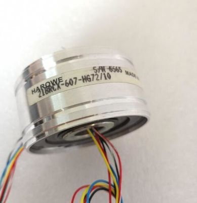
| Brand Name: | HAROWE |
| Certification: | CE |
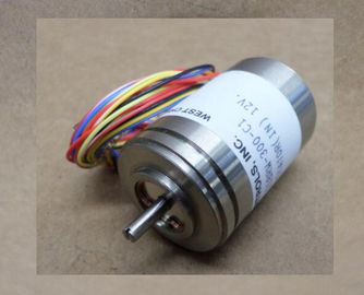
| Model Number: | 11BRW-300-F/10 |
| Minimum Order Quantity: | 1pcs |
|---|---|
| Packaging Details: | carton |
| Delivery Time: | in stock |
| Payment Terms: | T/T, Western Union, MoneyGram |
| Supply Ability: | 100pcs/week |
| HAROWE: | HAROWE | 11BRW-300-F/10: | 11BRW-300-F/10 |
|---|---|---|---|
| GERMANY: | GERMANY | Material: | Iron |
| Color: | Black | Temperature: | 20-90 |
| Wire: | Wire |
| V5.5 SP3 / - • PROFIBUS as of GSD version/GSD revision |
|
| V1.0 / V5.1 • PROFINET as of GSD version/GSD revision |
|
| V2.3 / - Operating mode • DI Yes |
Counter No
• Oversampling No
• MSI Yes
Power
Power available from the backplane bus 1.2 W
Power loss
Power loss, typ. 2.2 W; At 24 V DC; 6.0 W at 125 V AC
Digital inputs
Number of digital inputs 16
Digital inputs, parameterizable Yes
Source/sink input Yes
Input characteristic curve in accordance with
IEC 61131, type 3
Yes; at 24 V DConitoring the supply voltage No
• Wire-break Yes; To I < 550 µA
• Short-circuit No
Diagnostics indication LED
• RUN LED Yes; Green LED
• ERROR LED Yes; Red LED
• Monitoring of the supply voltage (PWRLED)
No
• Channel status display Yes; Green LED
• for channel diagnostics Yes; Red LED
• for module diagnostics Yes; Red LED
Potential separation
Potential separation channels
• between the channels Yes
• between the channels, in groups of 1
• between the channels and backplane bus Yes
Permissible potential difference
between different circuits 146 V DC/132 V AC
Isolation
Isolation tested with 2 000 V DC
Ambient conditions
Ambient temperature during operation
• horizontal installation, min. 0 °C
• horizontal installation, max. 60 °C
• vertical installation, min. 0 °C
• vertical installation, max. 40 °C
Decentralized operation
Prioritized startup Yes
Dimensions
Width 35 mm
Height 147 mm
Depth 129 mm
Weights
Weight, approx. 240 gThe following graphs show the number of channels (CHx) that can be used simultaneously in
relation to the mounting position of the /ET 200MP automation system and the
ambient temperature.The dimensional drawing of the module on the mounting rail, as well as a dimensional
drawing with open front cover, are provided in this appendix. Always observe the specified
dimensions for installations in cabinets, control rooms, etc.The data records of the module have an identical structure, regardless of whether you
configure the module with PROFIBUS DP or PROFINET IO.
Dependencies for configuration with GSD file
When a GSD file is used to configure a module, dependencies can arise when "assigning the
parameters".
There are no dependencies for this module. You can assign the individual parameters in any
combination.
Parameter assignment in the user program
You have the option to reconfigure the module in RUN (e.g. the input delay values of
selected channels can be edited without having an effect on the other channels).
Parameter assignment in RUN
The "WRREC" instruction is used to transfer the parameters to the module using data
records 0 to 15. The parameters set in STEP 7 do not change in the CPU, which means the
parameters set in STEP 7 are still valid after a restart.
The parameters are only checked for plausibility by the module after the transfer.
Output parameter STATUS
The module ignores errors that occurred during the transfer of parameters with the WRREC
instruction and continues operation with the previous parameter assignment. However, a
corresponding error code is written to the STATUS output parameter.
The description of the WRREC instruction and the error codes is available in the STEP 7
online help.
Operation of the module behind a PROFIBUS DP interface module
If the module is operated behind a PROFIBUS DP interface module, the parameter data
records 0 and 1 are not read back. You obtain the diagnostics data records 0 and 1 with the
read back parameter data records 0 and 1. You can find additional information in the
Interrupts section of the device manual for the PROFIBUS DP interface module in the
Internet.For the configuration with 1 x 16-channel, the parameters are located in data records 0 to 15
and are assigned as follows:
● Data record 0 for channel 0
● Data record 1 for channel 1
● …
● Data record 14 for channel 14
● Data record 15 for channel 15
For the configuration as a 4 x 8-channel module, the module has 4 submodules with eight
channels each. The parameters for the channels are located in data records 0 to 7 and are
assigned as follows:
● Data records 0 to 7 for channels 0 to 7 (submodule 1)
● Data records 0 to 7 for channels 8 to 15 (submodule 2)
Address the respective submodule for data record transfer.The figure below shows the structure of data record 0 for channel 0 as an example. The
structure is identical for channels 1 to 15. The values in byte 0 and byte 1 are fixed and may
not be changed.
Enable a parameter by setting the corresponding bit to "1".This manual contains notices you have to observe in order to ensure your personal safety, as well as to prevent
damage to property. The notices referring to your personal safety are highlighted in the manual by a safety alert
symbol, notices referring only to property damage have no safety alert symbol. These notices shown below are
graded according to the degree of danger.
DANGER
indicates that death or severe personal injury will result if proper precautions are not taken.
WARNING
indicates that death or severe personal injury may result if proper precautions are not taken.
CAUTION
indicates that minor personal injury can result if proper precautions are not taken.
NOTICE
indicates that property damage can result if proper precautions are not taken.