|
| Place of Origin: | GERMANY |
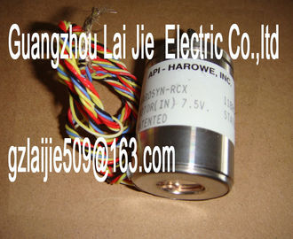
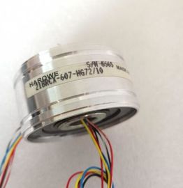
| Brand Name: | HAROWE |
| Certification: | CE |
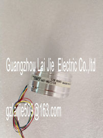
| Model Number: | 11BRW-300-F-1/10 |
| Minimum Order Quantity: | 1pcs |
|---|---|
| Packaging Details: | carton |
| Delivery Time: | in stock |
| Payment Terms: | T/T, Western Union, MoneyGram |
| Supply Ability: | 100pcs/week |
| HAROWE: | HAROWE | 11BRW-300-F-1/10: | 11BRW-300-F-1/10 |
|---|---|---|---|
| GERMANY: | GERMANY | Material: | Iron |
| Color: | Black | Temperature: | 20-90 |
| Wire: | Wire | Dimension: | 90mm |
| error (e.g., wire break). Flashes Flashes |
|
| Hardware defective. Replace the module. Status of the input signal. --- On |
|
| 1 = Status of the input signal. --- |
On
Diagnostics: Wire break or hardware interrupt
lost
Check the wiring. When using simple switches,
disable diagnostics or connect a resistor to the
encoder contacts.Digital input module DI 16x24...125VUC HF supports diagnostic and hardware interrupts.
You can find detailed information on the error event in the error organization block with the
"RALRM" instruction (read additional interrupt info) and in the STEP 7 online help.
Diagnostics interrupt
The module generates a diagnostic interrupt at the following events:
● Wire break
● Parameter assignment error
● Hardware interrupt lostThe module generates a hardware interrupt at the following events:
● Rising edge
● Falling edge
● Rising and falling edge
The module channel that triggered the hardware interrupt is entered in the start information
of the organization block. The following figure shows the assignment to the bits of double
word 8 in local dataAdditional interrupt info for hardware interrupts
of the I/O module
2
The channel that triggered the hardware interrupt follows.
Channel B#16#00 to B#16#0F Number of the event-triggering channel (channel
0 to channel 15 of the module)
1
It follows the error event that triggered the hardware interrupt.
Event B#16#01 Rising edge 1
B#16#02 Falling edgeA diagnostics alarm is generated and the ERROR LED flashes for each diagnostics event on
the module. The diagnostics alarms can be read out in the diagnostics buffer of the CPU, for
example. You can evaluate the error codes with the user program.
If the module is operated distributed with PROFIBUS DP in an ET 200MP system, you have
the option to read out diagnostics data with the instruction RDREC or RD_REC using data
record 0 and 1. The structure of the data records is available on the Internet in the "Manual
for interface module IM 155-5 DP ST (6E155-5BA00-0AB0)Impedance of encoder circuit too high Use a different encoder type or modify the wiring,
for example, using cables with larger cross-section
Wire break between the module and
sensor
Connect the cable
Channel not connected (open) • Disable diagnostics
• Connect encoder contacts with resistor:
– 16 kΩ ... 21 kΩ with 1.0 W at 24 VUC
– 37 kΩ ... 53 kΩ with 0.5 W at 48 VUC
– 101 kΩ ... 156 kΩ with 0.25 W at 125 VUC
Parameter assignment
error
10H • The module cannot evaluate parameters
for the channel
• Incorrect parameter assignment
Correct the parameter assignment
Hardware interrupt
lost
16H The module cannot trigger an interrupt
because the previous interrupt was
not acknowledged; possibly a configuration
error
Change interrupt processing in the CPU and edit
the module parameters if necessary (the error persists
until the module is assigned new parameters)Product type designation DI 16x24 ... 125VUC HF
HW functional status FS01
Firmware version V1.0.0
• FW update possible Yes
Product function
• I&M data Yes; I&M0 to I&M3
Engineering with
• STEP 7 TIA Portal configurable/integrated
as of version
V13 SP1 / -
• STEP 7 configurable/integrated as of version