 |
| Place of Origin: | GERMANY |
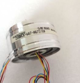
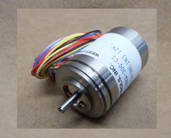
| Brand Name: | HAROWE |
| Certification: | CE |
| Model Number: | 11BRW-300-F1/1012V |
| Minimum Order Quantity: | 1pcs |
|---|---|
| Packaging Details: | carton |
| Delivery Time: | in stock |
| Payment Terms: | T/T, Western Union, MoneyGram |
| Supply Ability: | 100pcs/week |
| HAROWE: | HAROWE | 11BRW-300-F1/1012V: | 11BRW-300-F1/1012V |
|---|---|---|---|
| Material: | Iron | Color: | Black |
| Temperature: | 20-90 | Dimension: | 90mm |
| (PROFINET IO only) 2 x 8-channel with value status DI 16x24...125VUC HF S QI X |
|
| (PROFINET IO only) X |
|
| (PROFINET IO only) 1 x 16-channel with value status |
for module-internal shared input
with up to 4 submodules
DI 16x24...125VUC HF MSI X
(PROFINET IO only)
X
(PROFINET IO only)An additional bit is assigned to each channel for the value status. The value status bit
indicates if the read in digital value is valid. (0 = value is incorrect)The figure below shows the assignment of the address space for the configuration as a
16-channel module with value status. You can freely assign the start address for the module.
The addresses of the channels are derived from the start address.For the configuration as a 2 x 8-channel module, the channels of the module are divided into
multiple submodules. The submodules can be assigned to different IO controllers when the
module is used in a shared device.
The number of usable IO controllers depends on the interface module used. Please observe
the information in the manual for the particular interface module.
Contrary to the 1 x 16-channel module configuration, each of the two submodules has a
freely assignable start addressThe channels 0 to 15 of the module are copied in up to four submodules with configuration
1 x 16-channel module (Module-internal shared input, MSI). Channels 0 to 15 are then
available with identical input values in different submodules. These submodules can be
assigned to up to four IO controllers when the module is used in a shared device. Each
IO controller has read access to the same channels.
The number of IO controllers depends on the interface module being used. Please observe
the information in the manual for the particular interface module.
Value status (Quality Information, QI)
The meaning of the value status depends on the submodule involved.
For the 1st submodule (= basic submodule), the value status 0 indicates that the value is
incorrect.
For the 2nd to 4th submodule (=MSI submodule), the value status 0 indicates that the value
is incorrect or the basic submodule has not yet been configured (not ready).
The following figure shows the assignment of the address space with submodules 1 and 2
and the value statusThe following figure shows the assignment of the address space with submodules 3 and 4
and the value status.You can find information on the module-internal shared input/shared output (MSI/MSO)
function in the section Module-internal shared input/shared output (MSI/MSO) of the function
manual PROFINET with STEP 7 V13 The following figure shows the LED displays (status and error displays) of module.The tables below explain the meaning of the status and error displays.Voltage missing or too low at backplane bus. • Switch on the CPU and/or the system power
supply modules.
• Verify that the U connectors are inserted.
• Check to see if too many modules are inserted.
Flashes Off
The module starts and flashes until the valid
parameter assignment is set.
---
On Off
Module is ready.
On Flashes
Indicates module errors (at least one error at
one channel, e.g., wire break).
Evaluate the diagnostics data and eliminate the