|
| Place of Origin: | GERMANY |
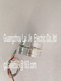
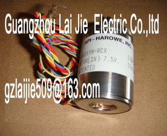
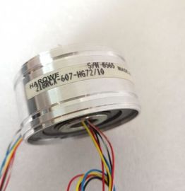
| Brand Name: | HAROWE |
| Certification: | CE |
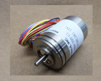
| Model Number: | 11BRW-300-F1/6 |
| Minimum Order Quantity: | 1pcs |
|---|---|
| Packaging Details: | carton |
| Delivery Time: | in stock |
| Payment Terms: | T/T, Western Union, MoneyGram |
| Supply Ability: | 100pcs/week |
| HAROWE: | HAROWE | 11BRW-300-F1/6: | 11BRW-300-F1/6 |
|---|---|---|---|
| GERMANY: | GERMANY | Material: | Iron |
| Color: | Black | Temperature: | 20-90 |
| Dimension: | 90mm | Wire: | Wire |
| systems. You configure your own download package with a few clicks. |
|
| In doing so you can select: ● Product images, 2D dimension drawings, 3D models, internal circuit diagrams, EPLAN |
|
| macro files ● Manuals, characteristics, operating manuals, certificates ● Product master data |
You can find the CAx Download Manager on the Internet The module has the following technical properties:
● 32 DO; electrically isolated in groups of 8
● Rated output voltage 24 V DC
● Rated output current 0.5 A per channel
● Assignable substitute values (per channel)
● Assignable diagnostics (per channel group)
● Suitable for solenoid valves, DC contactors, and indicator lights
● Hardware compatible to digital output module DQ 16x24VDC/0.5A ST (6E522-1BH00-
0AB0)
The module supports the following functions:Firmware update V1.0.0 or higher V12 or higher X
Identification data I&M0 to I&M3 V1.0.0 or higher V12 or higher X
Parameter assignment in RUN V1.0.0 or higher V12 or higher X
Isochronous mode V1.0.0 or higher V12 or higher ---
Module-internal Shared Output (MSO) V2.0.0 or higher V13 Update 3 or
higher
(PROFINET IO
only)
X
(PROFINET IO only)
Configurable submodules / submodules for
Shared Device
V2.0.0 or higher V13 Update 3 or
higher
(PROFINET IO
only)
X
(PROFINET IO only)
Configurable after interface module
IM 155-5 DP ST
V2.0.0 or higher V13 or higher X
You can configure the module with STEP 7 (TIA Portal) and with a GSD fileThe following accessories are supplied with the module and can also be ordered separately
as spare parts:
● Labeling strips
● U connector
● Universal front doorThe following component must be ordered separately:
Front connectors, including potential jumpers and cable ties
You can find more information on accessories in the Automation System his section contains the block diagram of the module and outlines various connection
options.
For more information on front connector wiring and creating cable shields, for example, refer
to the "Wiring" section in the Automation System manuals.
Abbreviations used
Meaning of the abbreviations used in the following figures:
xL+ Supply voltage connection
xM Ground connection
CHx Channel or display of the channel status
PWRx Display for the supply voltage (POWER)Use the potential jumpers supplied with the front connector if you want to connect the four
load groups to the same potential (non-isolated). This helps you to avoid having to terminate
two wires to one terminal.
Proceed as follows:
1. Connect the 24 V DC supply voltage to terminals 19 and 20.
2. Insert the potential jumpers between the following terminals:
– 9 and 29 (L+)
– 10 and 30 (M)
– 19 and 39 (L+)
– 20 and 40 (M).
3. Insert the jumpers between terminals 29 and 39, as well as 30 and 40.
4. Use the terminals 9 and 10 to loop the potential to the next moduleEnsure that the maximum current load of 8 A per potential jumper is not exceeded.When you assign the module parameters in STEP 7, you use various parameters to specify
the module properties. The following table lists the configurable parameters. The effective
range of the configurable parameters depends on the type of configuration. The following
configurations are possible:
● Central operation with a CPU