 |
| Place of Origin: | GERMANY |
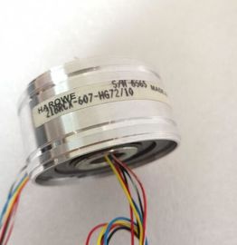
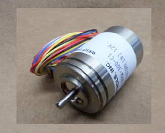
| Brand Name: | HAROWE |
| Certification: | CE |
| Model Number: | 11BRW300F5810 |
| Minimum Order Quantity: | 1pcs |
|---|---|
| Packaging Details: | carton |
| Delivery Time: | in stock |
| Payment Terms: | T/T, Western Union, MoneyGram |
| Supply Ability: | 100pcs/week |
| HAROWE: | HAROWE | 11BRW300F5810: | 11BRW300F5810 |
|---|---|---|---|
| Material: | Iron | Color: | Black |
| Temperature: | Iron | Dimension: | 90mm |
| Germany: | Germany | Wire: | Wire |
| Between the channels No Between the channels, in groups of 8 |
|
| Between the channels and the backplane bus Yes Permitted potential difference |
|
| Between different circuits 75 V DC / 60 V AC (basic isolation) Isolation |
Isolation tested with 707 V DC (type test)
Distributed mode
Prioritized startup Yes
Dimensions
Width 35 mm
Height 147 mm
Depth 129 mm
Weights
Weight, approx. 280 gHorizontal mounting position
② Vertical mounting position
Figure 6-1 Details on aggregate current of outputs (per groupThe dimensional drawing of the module on the mounting rail, as well as a dimensional
drawing with open front cover, are provided in the appendix. Always observe the specified
dimensions for installations in cabinets, control rooms, etc.Dimensional drawing of the DQ 32x24VDC/0.5A ST moduleDimensional drawing of the DQ 32x24VDC/0.5A ST module, side view with open front
panelThe data records of the module have an identical structure, regardless of whether you
configure the module with PROFIBUS DP or PROFINET IO.
Dependencies for configuration with GSD file
When a GSD file is used to configure a module, dependencies can arise when "assigning the
parameters".
There are no dependencies for this module. You can assign the individual parameters in any
combination.
Parameter assignment in the user program
You have the option of reassigning the module parameters in RUN (e.g., the reaction of the
individual channels to CPU STOP can be changed in RUN without affecting the other
channels)
Parameter assignment in RUN
The WRREC instruction is used to transfer the parameters to the module using data records
64 to 95. The parameters set in STEP 7 do not change in the CPU, which means the
parameters set in STEP 7 are still valid after a restart.
The parameters are only checked for plausibility by the module after the transferThe module ignores errors that occurred during the transfer of parameters with the WRREC
instruction and continues operation with the previous parameter assignment. However, a
corresponding error code is written to the STATUS output parameter.
The description of the WRREC instruction and the error codes is available in the STEP 7
online help.
Operation of the module behind a PROFIBUS DP interface module
If the module is operated behind a PROFIBUS DP interface module, the parameter data
records 0 and 1 are not read back. You get the diagnostics data records 0 and 1 for the read
back parameter data records 0 and 1. You can find more information in the Interrupts section
of the PROFIBUS DP interface module device manual on the Internet For the configuration as a 1 x 32-channel module, the parameters are located in data
records 64 to 95 and are assigned as follows:
● Data record 64 for channel 0
● Data record 65 for channel 1
● …
● Data record 94 for channel 30
Data record 95 for channel 31
For the configuration as a 4 x 8-channel module, the module has 4 submodules with eight
channels each. The parameters for the channels are located in data records 64 to 71 and
are assigned as follows:
● Data records 64 to 71 for channels 0 to 7 (submodule 1)
● Data records 64 to 71 for channels 8 to 15 (submodule 2)
● Data records 64 to 71 for channels 16 to 23 (submodule 3)
● Data records 64 to 71 for channels 24 to 31 (submodule 4)
Address the respective submodule for data record transfer.The example in the following figure shows the structure of data record 64 for channel 0. The
structure of channels 1 to 31 is identical. The values in byte 0 and byte 1 are fixed and may
not be changed.
Enable a parameter by setting the corresponding bit to "1n the product "Digital Modules, Analog Modules, Technological Modules, Communication
Modules and Power Supply Modules of the SIMATIC , ET 200MP", Copyright
AG, 2013 - 2014 (hereinafter "Product"), the following Open Source Software is
used either unchanged or in a form that we have modified, and additionally the other License
Software noted below.
Liability for Open Source Software
Open Source Software is provided free of charge. We are liable for the Product including
Open Source Software contained in accordance with the license conditions applicable to the
Product. Any liability for use of Open Source Software beyond the program flow intended for
the Product is explicitly excluded.
We do not provide any technical support for the Product if it has been modifiedThis manual contains notices you have to observe in order to ensure your personal safety, as well as to prevent
damage to property. The notices referring to your personal safety are highlighted in the manual by a safety alert
symbol, notices referring only to property damage have no safety alert symbol. These notices shown below are
graded according to the degree of danger.
DANGER
indicates that death or severe personal injury will result if proper precautions are not taken.
WARNING
indicates that death or severe personal injury may result if proper precautions are not taken.
CAUTION
indicates that minor personal injury can result if proper precautions are not taken.
NOTICE
indicates that property damage can result if proper precautions are not taken.