|
| Place of Origin: | GERMANY |
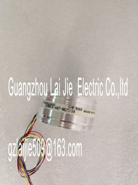
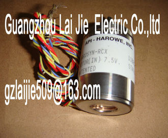
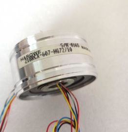
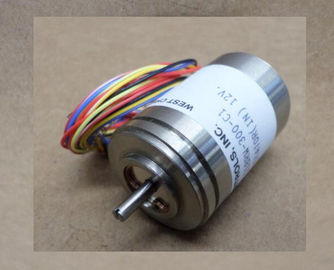
| Brand Name: | HAROWE |
| Certification: | CE |
| Model Number: | 11BRW-300-F79/10 |
| Minimum Order Quantity: | 1pcs |
|---|---|
| Packaging Details: | carton |
| Delivery Time: | in stock |
| Payment Terms: | T/T, Western Union, MoneyGram |
| Supply Ability: | 100pcs/week |
| HAROWE: | HAROWE | 11BRW-300-F79/10: | 11BRW-300-F79/10 |
|---|---|---|---|
| GERMANY: | GERMANY | Material: | Iron |
| Color: | Black | Temperature: | 20-90 |
| Wire: | Wire | Dimension: | 90mm |
| nd commissioning of the SIMATIC and ET 200MP systems. The STEP 7 online help supports you in the configuration and programming. |
|
| Device information Manuals contain a compact description of the module-specific information, such as |
|
| properties, terminal diagrams, characteristics, technical specifications. General information |
The function manuals contain detailed descriptions on general topics regarding the SIMATIC
and ET 200MP systems, e.g. diagnostics, communication, Motion Control, Web
server.
You can download the documentation free of charge from the Internet Changes and supplements to the manuals are documented in a Product InformationThe Manual Collection contains the complete documentation on the SIMATIC
automation system and the ET 200MP distributed I/O system gathered together in one file.
You can find the Manual Collection on the Internet The My Documentation Manager is used to combine entire manuals or only parts of these to
your own manual.
You can export the manual as PDF file or in a format that can be edited later.
You can find the My Documentation Manager on the Internet The CAx Download Manager is used to access the current product data for your CAx or CAe
systems.
You configure your own download package with a few clicks.
In doing so you can select:
● Product images, 2D dimension drawings, 3D models, internal circuit diagrams, EPLAN
macro files
● Manuals, characteristics, operating manuals, certificates
● Product master data
You can find the CAx Download Manager on the Internet Applications & Tools supports you with various tools and examples for solving your
automation tasks. Solutions are shown in interplay with multiple components in the system -
separated from the focus in individual products.
You can find Applications & Tools on the Internet The CAx Download Manager is used to access the current product data for your CAx or CAe
systems.
You configure your own download package with a few clicks.
In doing so you can select:
● Product images, 2D dimension drawings, 3D models, internal circuit diagrams, EPLAN
macro files
● Manuals, characteristics, operating manuals, certificates
● Product master data
You can find the CAx Download Manager on the Internet The digital module has the following technical properties:
● 32 DO; electrically isolated in groups of 8
● Rated output voltage 24 VDC
● Rated output current 0.5 A per channel
● Suitable for solenoid valves, DC contactors, and indicator lights
● Hardware compatible with digital output module DQ 16x24VDC/0.5A BA
(6E522-1BH10-0AA0)
The module supports the following functionsFirmware update V1.0.0 or higher V13 or higher X
Identification data I&M0 to I&M3 V1.0.0 or higher V13 or higher X
Module-internal Shared Output (MSO) V1.0.0 or higher V13 Update 3 or higher
(PROFINET IO only)
X
(PROFINET IO only)
Configurable submodules / submodules for
Shared Device
V1.0.0 or higher V13 Update 3 or higher
(PROFINET IO only)
X
(PROFINET IO onlyThe following accessories are supplied with the module and can also be ordered separately
as spare parts:
● Front connector (push-in terminals) including cable tie
● Labeling strips
● U connector
● Universal front door
You can find more information on accessories in the Automation System ET 200MP Distributed I/O System This section contains the block diagram of the module and outlines various connection
options.
For more information on front connector wiring and creating cable shields, for example, refer
to the "Wiring" section in the Automation Systemmanuals.Meaning of the abbreviations used in the following figure:
xL+ Supply voltage connector
xM Ground connector
CHx Channel or display for the channel status
PWRx Display for the supply voltage (POWER)
The example in the following figure shows the terminal assignment and the assignment of
the channels to the addresses (output byte a to output byte Upon activation of the 24 V supply voltage, there is a "1" signal at the module outputs for
approx. 50 μsThe module can be configured in various ways in STEP 7. Depending on the configuration,
additional/different addresses are assigned in the process image of the outputs/inputs.
Configuration options of DQ 32x24VDC/0.5A BA
You can configure the module with STEP 7 (TIA Portal) or with a GSD file.
When you configure the module by means of the GSD file, the configurations are available
under different abbreviations/module names.
The following configurations are possible:1 x 32-channel without value status DQ 32x24VDC/0.5A BA V13 or higher X
4 x 8-channel without value status DQ 32x24VDC/0.5A BA S V13 Update 3 or
higher
(PROFINET IO
only)
X
(PROFINET IO
only)
1 x 32-channel with value status for moduleinternal
Shared Output with up to 4 submodules
DQ 32x24VDC/0.5A BA M
SO
V13 Update 3 or
higher
(PROFINET IO
only)
X