 |
| Place of Origin: | GERMANY |
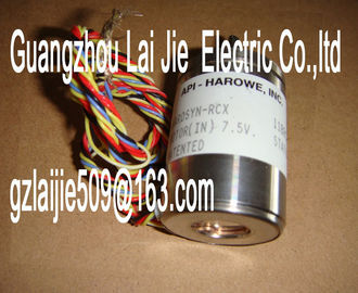
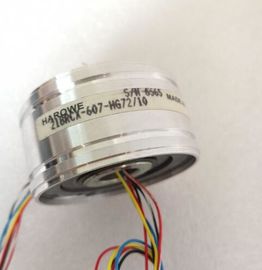
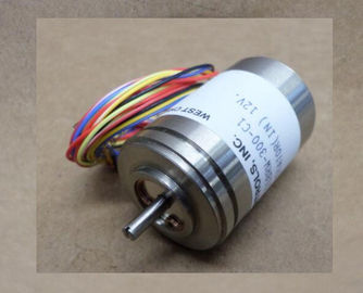
| Brand Name: | HAROWE |
| Certification: | CE |
| Model Number: | 11BRW-300-F95A |
| Minimum Order Quantity: | 1pcs |
|---|---|
| Packaging Details: | carton |
| Delivery Time: | in stock |
| Payment Terms: | T/T, Western Union, MoneyGram |
| Supply Ability: | 100pcs/week |
| HAROWE: | HAROWE | Material: | Iron |
|---|---|---|---|
| Temperature: | 20-90 | Dimension: | 90mm |
| Wire: | Wire | Color: | Black |
| Germany: | Germany |
| (PROFINET IO onlyThe figure below shows the address space assignment for configuration as a 1 x 32-channel |
|
| module. You can freely assign the start address for the module. The addresses of the channels are based on the start address. |
|
| The letters "a" to "d" are printed on the module. "AB a", for example, stands for module start address output byte aFor the configuration as a 4 x 8-channel module, the channels of the module |
are divided into
multiple submodules. The submodules can be assigned to different IO controllers when the
module is used in a Shared Device.
The number of usable submodules depends on the interface module used. Please observe
the information in the manual for the particular interface module.
Unlike the 1 x 32-channel module configuration, each of the four submodules has a freely
assignable start address.channels 0 to 31 of the module are copied to multiple submodules. Channels 0 to 31 are
then available with identical values in various submodules. These submodules can be
assigned to up to four IO controllers when the module is used in a Shared Device:
● The IO controller to which submodule 1 is assigned has write access to outputs 0 to 31.
● The IO controllers to which submodule 2, 3, or 4 is assigned have read access to outputs
0 to 31.
The number of usable submodules depends on the interface module used. Please observe
the information in the manual for the particular interface module.
Value status (Quality Information, QI)
The meaning of the value status depends on the submodule involved.
For the 1st submodule (=basic submodule), the value status 1 indicates that the output value
specified by the user program is actually output at the module terminal.
Possible causes for value status = 0:
● Value is incorrect, for example, because the supply voltage is missing.
● IO controller of the basic submodule is in STOP mode.
For the 2nd to 4th submodule (=MSO submodule), the value status 1 indicates that the
output value specified by the user program is actually output at the module terminal.
Possible causes for value status = 0:
● Value is incorrect, for example, because the supply voltage is missing.
● IO controller of the basic submodule is in STOP mode.
● The basic submodule is not yet configuredThe figure below shows the assignment of the address space for submodules 1 and 2.The module has no selectable diagnostics. Diagnostics alarms, for example, cannot be
output with STEP 7 (TIA Portal).
5.1 Status and error displays
LED displays
The figure below shows you the LED displays (status and error displays) of the
DQ 32x24VDC/0.5A BA.The tables below explain the meaning of the status and error displays.
LED RUN/ERROR
Table 5- 1 RUN/ERROR status and error displays
LED Meaning Remedy
RUN ERROR
Off Off
Voltage missing or too low at backplane bus. • Switch on the CPU and/or the system power
supply modules.
• Verify that the U connectors are inserted.
• Check to see if too many modules are inserted.
Flashes Off
Module is starting up. ---
On Off
Module is ready.
Flashes Flashes
Hardware defective. Replace the module.The tables below explain the meaning of the status and error displays.
LED RUN/ERROR
Table 5- 1 RUN/ERROR status and error displays
LED Meaning Remedy
RUN ERROR
Off Off
Voltage missing or too low at backplane bus. • Switch on the CPU and/or the system power
supply modules.
• Verify that the U connectors are inserted.
• Check to see if too many modules are inserted.
Flashes Off
Module is starting up. ---
On Off
Module is ready.
Flashes Flashes
Hardware defective. Replace the module.Firmware version V1.0.0
Product function
I&M data Yes
Engineering with
STEP 7 TIA Portal can be configured/integrated
as of version
V13 / V13
STEP 7 can be configured/integrated as of version V5.5 SP3 / -
Operating mode
MSO Yes
Supply voltage
Type of supply voltage DC
Rated value (DC) 24 V
Permitted range, low limit (DC) 20.4 V
Permitted range, high limit (DC) 28.8 V
Reverse polarity protection Yes; with internal protection with 7 A per group
Input current
Current consumption, max. 60 A
Power
Power taken from the backplane bus 1.15 W
Power loss
Power loss, typ. 3.8 W
Digital outputs
Type of digital output Transistor
Number of outputs 32
Sourcing output Yes
Digital outputs, configurable No
Short-circuit protection Yes
• Response threshold, typ. 1 A
Limitation of inductive shutdown voltage to L+ (-53 V)