|
| Place of Origin: | GERMANY |
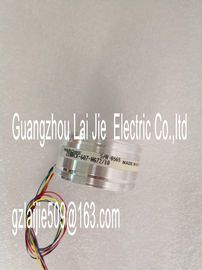
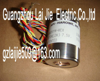
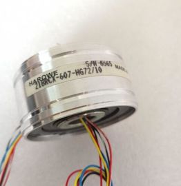
| Brand Name: | HAROWE |
| Certification: | CE |
| Model Number: | 15BRCX-320-J17 |
| Minimum Order Quantity: | 1pcs |
|---|---|
| Packaging Details: | carton |
| Delivery Time: | in stock |
| Payment Terms: | T/T, Western Union, MoneyGram |
| Supply Ability: | 100pcs/week |
| HAROWE15BRCX-320-J17: | HAROWE | 15BRCX-320-J17: | 15BRCX-320-J17 |
|---|---|---|---|
| Material: | Iron | Color: | Black |
| Temperature: | 20-90 | Wire: | Wire |
| Dimension: | 90mm | Germany: | Germany |
| The following figure shows the assignment of the address space for the configuration as a 16-channel module with value status. You can freely assign the start address for the module. |
|
| The addresses of the channels are derived from the start address. The letters "a to d" are printed onto the module. "For example, AB a" stands for module start |
|
| address output byte a.For the configuration as a 2 x 8-channel module, the channels of the module are divided into |
multiple submodules. The submodules can be assigned to different IO controllers when the
module is used in a shared device.
The number of usable submodules is dependent on the interface module used. Please
observe the information in the manual for the particular interface module.
Contrary to the 1 x 16-channel module configuration, each of the two submodules has a
freely assignable start address. The addresses for the respective value status of a
submodule can also be assigned by the user.Address space for configuration as 2 x 8-channel DQ 32x24VDC/0.5A ST S QI with value
statusFor the configuration as a 1 x 16-channel module (module-internal shared output, MSO),
channels 0 to 15 of the module are copied to multiple submodules. Channels 0 to 16 are
then available with identical values in various submodules. These submodules can be
assigned to up to four IO controllers when the module is used in a shared device:
● The IO controller to which submodule 1 is assigned has write access to outputs 0 to 15.
● The IO controllers to which submodule 2, 3, or 4 is assigned have read access to outputs
0 to 15.
The number of usable submodules is dependent on the interface module used. Observe the
information in the manual for the particular interface module.
Value status (Quality Information, QI)
The meaning of the value status depends on the submodule on which it occurs.
For the first submodule (=basic submodule), the value status 0 indicates that the value is
incorrect or that the IO controller of the basic submodule is in STOP state.
For the 2nd to 4th submodule (=MSO submodule), the value status 0 indicates that the value
is incorrect or one of the following errors has occurred:
● The basic submodule is not yet configured (not ready).
● The connection between the IO controller and the basic submodule has been interrupted.
● The IO controller of the basic submodule is in STOP or POWER OFF state.The following figure shows the assignment of the address space for submodules 1 and 2 and
the value status.Address space for configuration as 1 x 16-channel DQ 16x24VDC/0.5A ST S MSO with
value statusThe following figure shows the assignment of the address space with submodules 3 and 4
and the value status.The following figure shows the LED displays (status and error displays) of
DQ 16x24VDC/0.5A ST.
The following tables explain the meaning of the status and error displays. Remedial
measures for diagnostic alarms can be found in section Diagnostic alarms (Page 23).
RUN and ERROR LED
Table 5- 1 Status and error displays RUN and ERROR he module starts and flashes until the valid
parameter assignment is set.
---
On Off
Module is configured
On Flashes
Indicates module errors (at least one error at
one channel, e.g., short-circuit to ground).
Evaluate the diagnostics data and eliminate the