 |
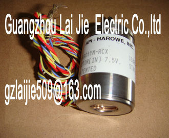
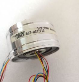
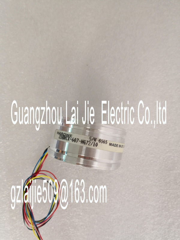
| Place of Origin: | GERMANY |
| Brand Name: | HAROWE |
| Certification: | CE |
| Model Number: | 11BRW-300-M-10B |
| Minimum Order Quantity: | 1pcs |
|---|---|
| Packaging Details: | carton |
| Delivery Time: | in stock |
| Payment Terms: | T/T, Western Union, MoneyGram |
| Supply Ability: | 100pcs/week |
| HAROWE: | HAROWE | 11BRW-300-M-10B: | 11BRW-300-M-10B |
|---|---|---|---|
| Material: | Iron | Germany: | Germany |
| Temperature: | 20-90 | Dimension: | 90mm |
| Wire: | Wire |
| You configure this function instead of programming. | |
| Monitoring" of each individual channel is possible. You can select which outputs are "monitored". |
|
| You can adapt the plant configuration flexibly and individually. |
Easy to service and maintain. You can enable and disable the switching cycle counter via
the user program.
● Increase in plant availability. You can schedule actuator replacement in advance for the
next maintenance cycle.
Requirement
Firmware version as of V1.1.0 of the module.
Configuration
You configure the switching cycle counter with the following parameters:
● Switching cycle counter enabled/disabled
● Trigger maintenance interrupt when the limit is reached
● Set limit for maintenance interruptThe module counts the switching cycles by evaluating the rising edges of an output signal. If
the module detects a rising edge, the switching cycle counter (24-bit) for the respective
channel is incremented. After an overflow of the switching cycle counter, it starts again with
0.
If you activate the "Maintenance switching cycles" parameter, the "Limit warning" of the
maintenance interrupt is triggered when the limit is exceeded. Alternatively, activate the
maintenance interrupt in the parameter data sets starting at DS 64.
The current counter states are stored on the module cyclically (approx. every 20 seconds)
and retentively. The switching cycle counters are reset each time the module is restarted
(power off/on).
You activate the function with the "Switching cycle counter" parameter or in the parameter
data sets starting at DS 64.
You can read the current counter states with data set DS 129. Data set DS 129 contains the
counter status for each channel in UDINT format.
You can read the limits for each channel in UDINT format with data set DS 130.
Data set DS 131 enables you to overwrite the current counter value for each switching cycle
counter.
You can set a limit for each switching cycle counter with the "Switching cycle limit" parameter
or with data set DS 131.This section contains the block diagram of the module and outlines various wiring options.
You can find information on wiring the front connector, establishing a cable shield, etc. in the
system manual /ET 200MP The example in the following figure shows the terminal assignment and the assignment of
the channels to the addresses (output byte a and output byte b).Backplane bus interface MAINT LED maintenance display (yellow)
xL+ Supply voltage 24 V DC RUN Status display LED (green)
xM Ground ERROR Error display LED (red)
CHx Channel or channel status LED
(green/red)
PWR POWER supply voltage LED (green)
Figure 3-1 Block diagram and terminal assignmentWhen the 24 V supply voltage is switched on at each channel, there is a "1" signal at the
module outputs for approx. 50 μs.
Tip: Using the potential jumpers
If you want to supply both load groups with the same potential (non-isolated), use the
potential jumpers supplied with the front connector. This helps you to avoid having to
terminate two wires to one terminal.
Proceed as follows:
1. Connect the 24 V DC supply voltage to terminals 19 and 20.
2. Insert the potential jumpers between terminals
– 9 and 29 (L+)
– 10 and 30 (M)
– 19 and 39 (L+)
– 20 and 40 (M)
3. Insert the jumpers between terminals 29 and 39, as well as 30 and 40.
4. Use the terminals 19 and 20 to distribute the potential to the next module.Ensure that the maximum current load of 8 A per potential jumper is not exceededWhen you assign the module parameters in STEP 7, you use various parameters to specify
the module properties. The following table lists the configurable parameters. The effective
range of the configurable parameters depends on the type of configuration. The following
configurations are possible:
● Central operation with a CPU
● Distributed operation on PROFINET IO in an ET 200MP system
● Distributed operation on PROFIBUS DP in an ET 200MP system
For parameter assignment in the user program, the parameters are transferred to the