 |
| Place of Origin: | GERMANY |
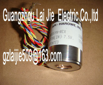
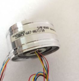
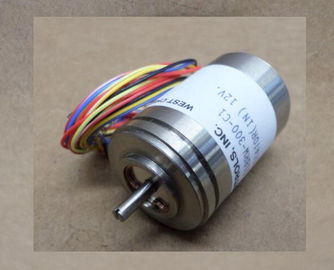
| Brand Name: | HAROWE |
| Certification: | CE |
| Model Number: | 11RCD-300-B-2A/3 |
| Minimum Order Quantity: | 1pcs |
|---|---|
| Packaging Details: | carton |
| Delivery Time: | in stock |
| Payment Terms: | T/T, Western Union, MoneyGram |
| Supply Ability: | 100pcs/week |
| HAROWE: | HAROWE | 11RCD-300-B-2A/3: | 11RCD-300-B-2A/3 |
|---|---|---|---|
| GERMANY: | GERMANY | Temperature: | 20-90 |
| Color: | Black | Dimension: | 90mm |
| Wire: | Wire |
| channels 0 to 15 of the module are copied to multiple submodules. Channels 0 to 15 are then available with identical values in various submodules. These submodules can be |
|
| assigned to up to four IO controllers when the module is used in a shared device: ● The IO controller to which submodule 1 is assigned has write access to outputs 0 to 15. |
|
| The IO controllers to which submodule 2, 3, or 4 is assigned have read access to outputs 0 to 15. |
The number of IO controllers depends on the interface module used. Observe the
information in the manual for the particular interface module.The meaning of the value status depends on the submodule on which it occurs.
For the first submodule (=basic submodule), the value status 0 indicates that the value is
incorrect or that the IO controller of the basic submodule is in STOP state.
For 2nd to 4th submodule (=MSO submodule), the value status 0 indicates that the value is
incorrect or one of the following errors has occurred:
● The basic submodule is not yet configured (not ready).
● The connection between the IO controller and the basic submodule has been interrupted.
● The IO controller of the basic submodule is in STOP or POWER OFF state.
The following figure shows the assignment of the address space for submodules 1 and 2 and
the value status.
Address space for configuration as 1 x 16-channel DQ 16x24VDC/0.5A HF S MSO with
value statusThe following figure shows the assignment of the address space with submodules 3 and 4
and the value status.You can find information on the Shared Input/Output (MSI/MSO) function in the section
Module-Internal Shared Input/Output (MSI/MSO) of the PROFINET with STEP 7 V13
The tables below explain the meaning of the status and error displays. Remedial measures
for diagnostic alarms can be found in section Diagnostic alarms (Page 28).
RUN and ERROR LED
Table 5- 1 Status and error displays RUN and ERROR
LED Meaning Solution
RUN ERROR
Off Off
Voltage missing or too low at backplane bus • Switch on the CPU and/or the system power
supply modules.
• Verify that the U connectors are inserted.
• Check to see if too many modules are inserted.
Flashes Off
The module starts and flashes until the valid
parameter assignment is set.
---
On Off
Module is configured
On Flashes
Indicates module errors (at least one error at
one channel, e.g., short-circuit to ground).
Evaluate the diagnostics data and eliminate the
error (e.g., check the cables).
Flashes Flashes
Hardware defective Replace the module.
LED MAINT
Table 5- 2 MAINT status display
LED MAINT Meaning Solution
Off
0 = No maintenance interrupt is pending. ---
On
1 = The maintenance interrupt "Limit value
warning" is pendingSupply voltage L+ too low or missing Check the L+ supply voltage.
On
Supply voltage L+ is present and OK0 = Status of the output signal ---
On
1 = Status of the output signal ---
On
• Wire break or short-circuit to ground
• Supply voltage L+ missing or too low
• Correct the process wiring
• Check the supply voltage.
5.2 Interrupts
The digital output module DQ 16x24VDC/0.5A HF supports diagnostic interrupts and
maintenance interrupts.
You can find detailed information on the event in the error organization block with the
"RALRM" instruction (read additional interrupt info) and in the STEP 7 online helpThe module generates a diagnostic interrupt at the following events:
● No supply voltage L+
● Short circuit to ground
● Wire break
● Parameter assignment error
Maintenance interrupt
The module generates a maintenance interrupt at the following events:
● Limit value warningA diagnostics alarm is generated and the ERROR LED flashes for each diagnostics event on
the module. You can read the diagnostics alarms, for example, in the diagnostics buffer of
the CPU. You can evaluate the error codes with the user program.
If the module is operated distributed with PROFIBUS DP in an ET 200MP system, you have
the option to read out diagnostics data with the instruction RDREC or RD_REC using data
record 0 and 1. The structure of the data records is available on the Internet in the "Manual
for interface module IM 155-5 DP ST (6E155-5BA00-0AB0)Short circuit to ground 1H Short-circuit or overload at the channel
Check the wiring/actuator. Check
the ambient temperature.
Wire break* 6H Actuator circuit impedance too high. Use different actuator type or wire
differently, e.g. use lines with bigger
cross-section
Wire break between the module and
actuator
Connect the cable
Channel not connected (open) • Disable diagnostics
• Connect a resistor to the actuator
contacts in the load resistance
range
Parameter assignment
error
10H • The module cannot evaluate parameters
for the channel.
• Incorrect parameter assignment
Correct the parameter assignment
Load voltage missing 11H Supply voltage L+ of the module is
missing
Connect supply voltage L+ to module/channel
Limit value warning 17H The configured limit for switching
cycles has been exceeded.
• Replace actuator as a precautionary
measure
• Reset counter with DS131