 |
| Place of Origin: | GERMANY |
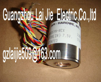
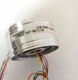
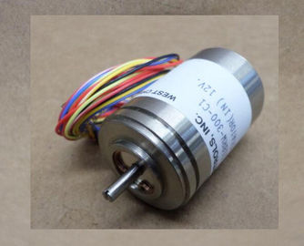
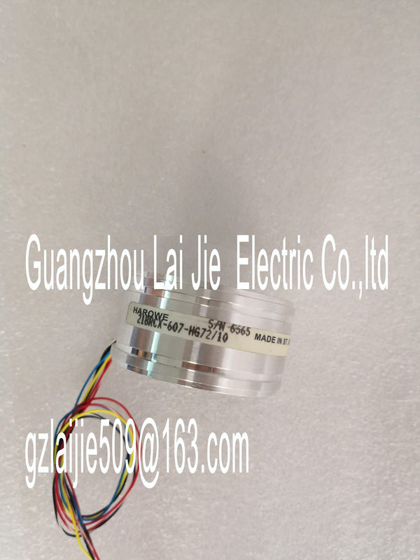
| Brand Name: | HAROWE |
| Certification: | CE |
| Model Number: | 15BRCX-401-A21/10 |
| Minimum Order Quantity: | 1pcs |
|---|---|
| Packaging Details: | carton |
| Delivery Time: | in stock |
| Payment Terms: | T/T, Western Union, MoneyGram |
| Supply Ability: | 100pcs/week |
| HAROWE: | HAROWE | 15BRCX-401-A21/10: | 15BRCX-401-A21/10 |
|---|---|---|---|
| Color: | Black | Temperature: | 20-90 |
| Wire: | Wire | Dimension: | 90mm |
| Germany: | Germany | Material: | Iron |
| error (e.g., check the cables). Flashes Flashes |
|
| Hardware defective Replace the module.Switch on the CPU and/or the system power | |
| supply modules. • Verify that the U connectors are inserted. |
Check to see if too many modules are inserted.Supply voltage L+ too low or missing Check the L+ supply voltage.
On
Supply voltage L+ is present and OK0 = Status of the output signal ---
On
1 = Status of the output signalDigital output module DQ 16x24VDC/0.5A ST supports diagnostic interrupts.
Diagnostic interrupt
The module generates a diagnostic interrupt at the following events:
● Missing supply voltage L+
● Short-circuit to ground
For more information on the error event, refer to the error OB with the "RALRM" instruction
(read additional interrupt info) and to the STEP 7 Online Help.
5.3 Diagnostics alarms
Diagnostics alarms
A diagnostics alarm is output for each diagnostics event and the ERROR LED flashes on the
module. The diagnostics alarms can, for example, be read from the diagnostics buffer of the
CPU. You can evaluate the error codes with the user program.
If the module is operated distributed with PROFIBUS DP in an ET 200MP system, you have
the option to read out diagnostics data with the instruction RDREC or RD_REC using data
record 0 and 1. The structure of the data records is available on the in the "Manual
for interface module IM 155-5 DP ST (6E155-5BA00-0AB0)Short-circuit or overload at the channel
Check the wiring/actuator. Check
the ambient temperature.
Load voltage missing 11H Supply voltage L+ of the module is
missing
Connect supply voltage L+ to module/channelHardware version E01
Firmware version V2.0.0
Product function
I&M data Yes; IM0 to IM3
Engineering with
STEP 7 TIA Portal can be configured/integrated
as of version
V12.0 / V12.0
STEP 7 can be configured/integrated as of version as of V5.5 SP3 / -
Operating mode
MSO Yes
Supply voltage
Type of supply voltage DC
Rated value (DC) 24 V
Valid range, low limit (DC) 20.4 V
Valid range, high limit (DC) 28.8 V
Reverse polarity protection Yes; through internal protection with 7 A per
group
Input current
Current consumption, max. 30 mA
Output voltage
Rated value (DC) 24 V
Power
Power consumption from the backplane bus 1.1 W
Power loss
Power loss, typ. 2 W
Digital outputs
Type of digital output Transistor
Number of outputs 16
Switching to P potential Yes
Digital outputs, configurable Yes
Short-circuit protection Yes; electronic clocking
• Response threshold, typ. 1 A
Limitation of inductive shutdown voltage to L+ (-53 V)
Control of a digital inputWith resistive load, max. 0.5 A
With lamp load, max. 5 W
Load resistance range
Low limit 48 Ω
High limit 12 kΩ
Output voltage
Type of output voltage DC
for signal "1", min. L+ (-0.8 V)
Output current
for signal "1" rated value 0.5 A
for signal "1" permissible range, max. 0.5 A
for signal "0" residual current, max. 0.5 mA
Output delay with resistive load
"0" to "1", max. 100 µs
"1" to "0", max. 500 µs
Parallel switching of 2 outputs
For logic operations Yes
For increased performance No
For redundant control of a load Yes
Switching frequency
With resistive load, max. 100 Hz
With inductive load, max. 0.5 Hz; acc. to IEC 947-5-1, DC13
With lamp load, max. 10 Hz