|
| Place of Origin: | GERMANY |
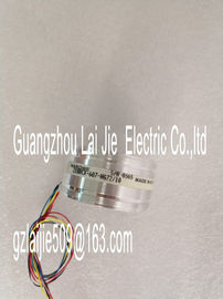
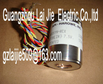
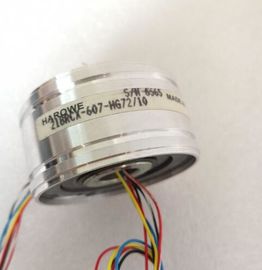
| Brand Name: | HAROWE |
| Certification: | CE |
| Model Number: | 15BRCX-402-A10A/10 |
| Minimum Order Quantity: | 1pcs |
|---|---|
| Packaging Details: | carton |
| Delivery Time: | in stock |
| Payment Terms: | T/T, Western Union, MoneyGram |
| Supply Ability: | 100pcs/week |
| HAROWE: | HAROWE | 15BRCX-402-A10A/10: | 15BRCX-402-A10A/10 |
|---|---|---|---|
| GERMANY: | GERMANY | Temperature: | 20-90 |
| Wire: | Wire | Dimension: | 90mm |
| Color: | Black | Material: | Iron |
| 16 digital outputs, electrically isolated in groups of 8 | |
| Rated output voltage 24 VDC ● Rated output current 0.5 A per channel |
|
| Suitable for solenoid valves, DC contactors, and indicator lights |
The module supports the following functions:You can configure the module with STEP 7 (TIA Portal) and with a GSD file.
Accessories
The following accessories are supplied with the module and can also be ordered separately
as spare parts:
● Front connector (push-in terminals) including cable tie
● Labeling strips
● U connector
● Universal front door
You can find more information on accessories in the Automation System This section contains the block diagram of the module and outlines various connection
options.
For more information on front connector wiring and creating cable shields, for example, refer
to the "Wiring" section in the Automation System Meaning of the abbreviations used in the following figure:
xL+ Supply voltage connector
xM Ground connector
CHx Channel or display for the channel status
PWRx Display for the supply voltage (POWER)
The example in the following figure shows the terminal assignment and the assignment of
the channels to the addresses (output byte a and output byte b)Upon activation of the 24 V supply voltage, there is a "1" signal at the module outputs for
approx. 50 μs.The module can be configured in various ways in STEP 7. Depending on the configuration,
additional/different addresses are assigned in the process image of the outputs/inputs.
Configuration options of DQ 16x24VDC/0.5A BA
You can configure the module with STEP 7 (TIA Portal) or with a GSD file.
When you configure the module by means of the GSD file, the configurations are available
under different abbreviations/module names.
The following configurations are possible: 16-channel without value status DQ 16x24VDC/0.5A BA V13 or higher X
2 x 8-channel without value status DQ 16x24VDC/0.5A BA
S
V13 Update 3 or
higher
(PROFINET IO only)
X
(PROFINET IO
only)
1 x 16-channel with value status for moduleinternal
Shared Output with up to 4 submodules
DQ 16x24VDC/0.5A BA
MSO
V13 Update 3 or
higher
(PROFINET IO only)
X
(PROFINET IO
only)The figure below shows the address space assignment for configuration as a 1 x 16-channel
module. You can freely assign the start address for the module. The addresses of the
channels are based on the start address.
The letters "a" to "d" are printed on the module. "AB a", for example, stands for module start
address output byte a.
For the configuration as a 2 x 8-channel module, the channels of the module are divided into
multiple submodules. The submodules can be assigned to different IO controllers when the
module is used in a Shared Device.
The number of usable submodules depends on the interface module used. Please observe
the information in the manual for the particular interface module.
Unlike the 1 x 16-channel module configuration, each of the two submodules has a freely
assignable start address● The IO controller to which submodule 1 is assigned has write access to outputs 0 to 15.
● The IO controllers to which submodules 2, 3 or 4 are assigned have write access to the
outputs 0 to 15.
The number of usable submodules depends on the interface module used. Please observe
the information in the manual for the particular interface module.
Value status (Quality Information, QI)
The meaning of the value status depends on the submodule involved.
For the 1st submodule (=basic submodule), the value status 1 indicates that the output value
specified by the user program is actually output at the module terminal.
Possible causes for value status = 0:
● Value is incorrect, for example, because the supply voltage is missing.
● IO controller of the basic submodule is in STOP mode.
For the 2nd to 4th submodule (=MSO submodule), the value status 1 indicates that the
output value specified by the user program is actually output at the module terminal.
Possible causes for value status = 0:
● Value is incorrect, for example, because the supply voltage is missing.
● IO controller of the basic submodule is in STOP mode.