 |
| Place of Origin: | GERMANY |
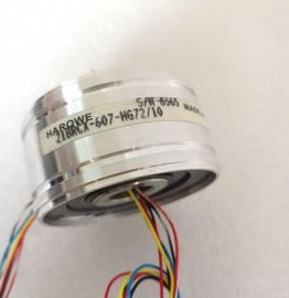
| Brand Name: | HAROWE |
| Certification: | CE |
| Model Number: | 15BRCX-402-L10S/8 |
| Minimum Order Quantity: | 1pcs |
|---|---|
| Packaging Details: | carton |
| Delivery Time: | in stock |
| Payment Terms: | T/T, Western Union, MoneyGram |
| Supply Ability: | 100pcs/week |
| HAROWE: | HAROWE | 15BRCX-402-L10S/8: | 15BRCX-402-L10S/8 |
|---|---|---|---|
| GERMANY: | GERMANY | Temperature: | 20-90 |
| Wire: | Wire | Dimension: | 90mm |
| Color: | Black | Material: | Iron |
| STEP 7 V13, SP1 or higher |
|
| STEP 7 , V12 or higher STEP 7 V5.5 SP3 or higher |
|
| with HSP 0119 GSD file in |
Firmware update V1.0.0 or higher X --- / X
Identification data I&M0 to I&M3 V1.0.0 or higher X --- / X
Reconfiguration in RUN V1.0.0 or higher X X
Module-internal Shared Output (MSO) V1.0.0 or higher X
(PROFINET IO only)
X
(PROFINET IO only)
Configurable submodules/submodules for
shared device
V1.0.0 or higher X
(PROFINET IO only)
X
(PROFINET IO only)
You can configure the module with STEP 7 and with a GSD fileThis section contains the block diagram of the module and outlines various wiring options.
You will find information on wiring the front connector, establishing a cable shield, etc in the
system manual /ET 200MP The example in the following figure shows the terminal assignment and the assignment of
the channels. The individual channels are connected with a TRIAC (Triode for Alternating
Current)TRIAC 16x CHx Channel or channel status LED (green)
② Backplane bus interface RUN Status display LED (green)
ERROR Fault display LED (red)
Figure 3-1 Block diagram and terminal assignmentWhen you assign the module parameters in STEP 7, you use various parameters to specify
the module properties. The table below lists the parameters that can be set. The effective
range of the configurable parameters depends on the type of configuration. The following
configurations are possible:
● Central operation with a CPU
● Distributed operation on PROFINET IO in an ET 200MP system
● Distributed operation on PROFIBUS DP in an ET 200MP system
For parameter assignment in the user program, the parameters are transferred to the
module using the WRREC instruction (reconfiguration in RUN) and data records; see
chapter Parameter assignment and structure of the parameter data records (Page 27). Determines the reaction of the output to the CPU going into STOP state or when the
connection to the CPU is interrupted.
4.3 Address space
The module can be configured differently in STEP 7; see following table. Depending on the
configuration, additional/different addresses are assigned in the process image output/input.
Configuration options of DQ 16x230VAC/1A ST
You can configure the module with STEP 7 or with a GSD file.
When you configure the module by means of the GSD file, the configurations are available
under different short designations/module names.
The following configurations are possible:1 x 16-channel without value status DQ 16x230VAC/1A ST X X
2 x 8-channel without value status DQ 16x230VAC/1A ST S X
(PROFINET IO only)
X
(PROFINET IO only)
1 x 16-channel with value status for
module-internal Shared Output with
up to 4 submodules
DQ 16x230VAC/1A ST MSO X
(PROFINET IO only)
X
(PROFINET IO only)
Value status (Quality Information, QI)
The value status is always activated for the DQ 16x230VAC/1A ST MSO.
An additional bit is assigned to each channel for the value status. The bit for the value status
indicates if the output value specified by the user program is actually pending at the module
terminal (0 = value is incorrect). The figure below shows the address space allocation for the configuration as 16-channel
module. You can freely assign the start address for the module. The addresses of the
channels are derived from the start address.
The letters "a to b" are printed onto the module. "For example, AB a" stands for module start
address output byte a.