 |
| Place of Origin: | GERMANY |
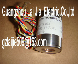
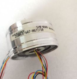
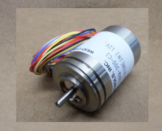
| Brand Name: | HAROWE |
| Certification: | CE |
| Model Number: | 15BRCX-500-F13/10 |
| Minimum Order Quantity: | 1pcs |
|---|---|
| Packaging Details: | carton |
| Delivery Time: | in stock |
| Payment Terms: | T/T, Western Union, MoneyGram |
| Supply Ability: | 100pcs/week |
| HAROWE: | HAROWE | 15BRCX-500-F13/10: | 15BRCX-500-F13/10 |
|---|---|---|---|
| GERMANY: | GERMANY | Material: | Iron |
| Color: | Black | Temperature: | 20-90 |
| Wire: | Wire | Dimension: | 90mm |
| nline help supports you in the configuration and programming. Device information |
|
| Product manuals contain a compact description of the module-specific information, such as | |
| properties, wiring diagrams, characteristics and technical specifications. General information |
The function manuals contain detailed descriptions on general topics regarding the SIMATIC
and ET 200MP systems, e.g. diagnostics, communication, Motion Control, Web
server.
You can download the documentation free of charge from the he Manual Collection contains the complete documentation on the SIMATIC
automation system and the ET 200MP distributed I/O system gathered together in one file.
You can find the Manual Collection on the The My Documentation Manager is used to combine entire manuals or only parts of these to
your own manual.
You can export the manual as PDF file or in a format that can be edited later.
You can find the My Documentation Manager on the Application examples support you with various tools and examples for solving your
automation tasks. Solutions are shown in interplay with multiple components in the system -
separated from the focus in individual products.
You can find application examples on the The CAx Download Manager is used to access the current product data for your CAx or CAe
systems.
You configure your own download package with a few clicks.
In doing so you can select:
● Product images, 2D dimension drawings, 3D models, internal circuit diagrams, EPLAN
macro files
● Manuals, characteristics, operating manuals, certificates
● Product master data
You can find the CAx Download Manager on the With the TIA Selection Tool, you can select, configure and order devices for Totally
Integrated Automation (TIA).
This tool is the successor of the SIMATIC Selection Tool and combines the known
configurators for automation technology into one tool.
With the TIA Selection Tool, you can generate a complete order list from your product
selection or product configuration.
You can find the TIA Selection Tool on the vThe module has the following technical properties:
● 16 digital outputs (relays)
● Supply voltage of the 24 V DC relay coils
● Rated output voltage 230 V AC (24 V DC up to 120 V DC/24 V AC up to 230 V AC)
● Rated output current 2A (per channel)
● Configurable substitute values (per channel)
● Configurable diagnostics
● Suitable for solenoid valves, DC contactors, and indicator lights
The module supports the following functionsFirmware update V1.0.0 or higher X --- / X
Identification data I&M0 to I&M3 V1.0.0 or higher X --- / X
Reconfiguration in RUN V1.0.0 or higher X X
Module-internal Shared Output (MSO) V1.0.0 or higher X
(PROFINET IO only)
X
(PROFINET IO only)
Configurable submodules / submodules for
Shared Device
V1.0.0 or higher X
(PROFINET IO only)
X
(PROFINET IO only)
You can configure the module with STEP 7 and with a GSD file.
Accessories
The following accessories are supplied with the module and can also be ordered separately
as spare parts:
● Labeling strips
● U connector
● Universal front door
Other components
The following component must be ordered separately:
Front connectors, including potential jumpers and cable ties
For more information on accessories, refer to the /ET 200MP system manual This section contains the block diagram of the module and outlines various wiring options.
You will find information on wiring the front connector, establishing a cable shield, etc in the
/ET 200MP system manual The example in the following figure shows the terminal assignment and the assignment of
the channels. The individual channels are connected with a relayNote that the 24 V DC supply voltage for this module must always be supplied by terminals
19/20 and 39/40. Use the supplied potential jumpers for this purpose.Relay 16x CHx Channel or channel status LED (green)
② Backplane bus interface RUN Status display LED (green)
L+ Power supply 24 V DC for relay contacts ERROR Fault display LED (red)
M Ground PWR Supply voltage POWER LED (green)Use the potential jumpers supplied with the front connector if you want to distribute the 24 V
DC supply voltage to a neighboring module. This helps you to avoid having to terminate two
wires to one terminal.
Proceed as follows:
1. Connect the 24 V DC supply voltage to terminals 19 and 20.
2. Insert the potential jumpers between terminals 19 and 39 (L+) and between terminals 20
and 40 (M).
3. Use the terminals 39 and 40 to loop the potential to the next module.Ensure that the maximum current load of 8 A per potential jumper is not exceeded.When you assign the module parameters in STEP 7, you use various parameters to specify
the module properties. The table below lists the parameters that can be set. The effective
range of the configurable parameters depends on the type of configuration. The following
configurations are possible: